Basic Current Mirrors
Current source 很有用,前几章中电流源有如下作用:
- 为电路提供合适的静态工作点
- 起一个大电阻的作用,但不消耗过多的电压 裕度
- 工作在饱和区的MOS管可以当作电流源
但怎么使得 MOSFET operate as a stable current source? 最简单的,就是用 resistive bias (Fig. 5.2)
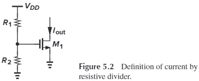
但式中的 $\mu_n,V_\tx{TH},R$ 都是会随温度变化的,所以这种方法并不可靠。
实际在电路中,有一个标准电流源 $I_\tx{REF}$(在 Chapter 12 会介绍),我们可以用利用 $I_\tx{REF}$ 复制出其他电流源:
- 利用 $I_D$-$V_{GS}$ 关系,令 $I_D=I_\tx{REF}$,得到固定的 $V_{GS}$(Fig. 5.5a)
- 我们之前都是 $V_{GS}$ 决定 $I_D$,这里是反过来的
- 但这要求 MOS 是 dioded connected(保证它处在饱和区)
- 将 $V_{GS}$ 作为另一个管子的 $V_{GS}$,得到 $I_\tx{out}$(Fig. 5.5b)
%20Diode-connected%20deviceproviding%20inverse%20function;%20(b)%20basic%20current%20mirror.jpg)
Fig. 5.5(b) 就是 电流镜 current mirror。公式表述为:
\[\begin{aligned} I_\tx{REF} &= \frac{1}{2} \mu_n C_\tx{ox} \left(\frac{W}{L}\right)_1(V_{GS}-V_\tx{TH})^2\\ I_\tx{out} &= \frac{1}{2} \mu_n C_\tx{ox} \left(\frac{W}{L}\right)_2(V_{GS}-V_\tx{TH})^2 \end{aligned}\]从而:
\[I_\tx{out} =\frac{(W/L)_2}{(W/L)_1} I_\tx{REF}\]
find the drain current of $M_4$ if all of the transistors are in saturation.
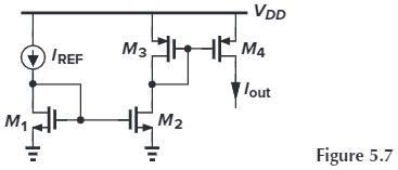
首先,$I_{D2}=\frac{(W/L)_2}{(W/L)_1} I_\tx{REF}$,然后,$I_{D4}=\frac{(W/L)_4}{(W/L)_3} I_{D3}$,所以 $I_{D4}=\alpha\beta I_\tx{REF}$,$\alpha,\beta$ 是对应的 $W/L$ 比例
我们只需要记住 $I_D$ 与 $(W/L)$ 成比例即可。
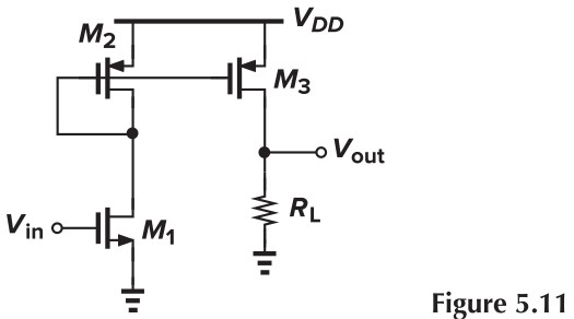
另外注意到电流镜对电流有缩放的作用,利用这点可以提高增益(如下 Fig. 5.11)
当尺寸缩小时,$W/L$ 很难精确控制(因为 $L_\tx{eff} = L_\tx{drawn} - 2L_D$,$L_D$ 会导致误差),此时我们可以采用多管并联/串联的方式来调整 W 或 L(Fig. 5.10)
%20half-width%20device%20and%20(b)%20series%20transistors.jpg)
Cascode Current Mirrors
上面看起来很美好,但如果考虑上沟道长度调制效应:
\[\begin{aligned} I_{D1} &= \frac{1}{2} \mu_n C_\tx{ox} \left(\frac{W}{L}\right)_1(V_{GS}-V_\tx{TH})^2(1+\lambda V_{DS1})\\ I_{D2} &= \frac{1}{2} \mu_n C_\tx{ox} \left(\frac{W}{L}\right)_2(V_{GS}-V_\tx{TH})^2(1+\lambda V_{DS1}) \end{aligned}\]就会发现:
\[\frac{I_{D2}}{I_{D1}}=\frac{(W/L)_2}{(W/L)_1}\cdot \frac{1+\lambda V_{DS2}}{1+\lambda V_{DS1}}\]$V_{DS1}=V_{GS1}$ 是个恒定值,但 $V_{DS2}$ 却可能会变。为了抑制这种效应,我们有两种方法:
- 方法一:令 $V_{DS2}=V_{DS1}=V_{GS1}$
- 方法二:令 $V_{DS1}=V_{DS2}$
当然啦,我们并不是把对应点直接连起来,而是令上面电压尽可能接近。
方法一
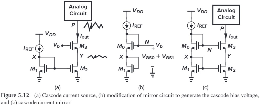
Cascode device can shiel a current source, thereby reducing the voltage variations across it (Fig. 5.12a) To ensure $V_{DS2}=V_{DS1}$, we must generate $V_b-V_{GS3}=V_{DS1}(=V_{GS1})$, i.e $V_b=V_{GS3}+V_{GS1}$. By adding $M_0$, we have $V_b = V_{GS0}+V_{GS1}$ (Fig. 5.12c), therefore $V_Y=V_X$
补充:对宽长比的要求:$L_2=L_1$,$L_3=L_0$,$W_3/W_0 = W_2/W_1$(利用多管并联来提高精确度)
We can plot $I_X$ s $V_X$ drops:
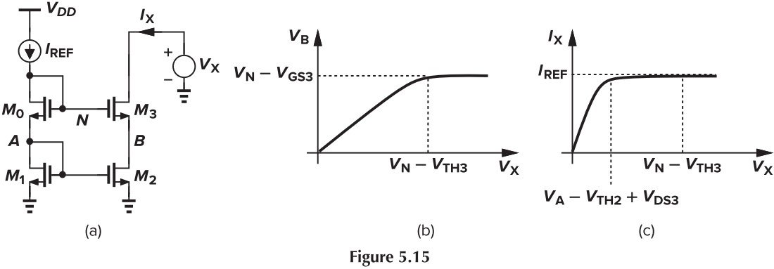
这种方法的优点是:阻抗高、输出电流值精确,但这是以牺牲电压裕度为代价的。我们可以比较一下 Fig. 5.14 (a) 和 (b) 的电压裕度:
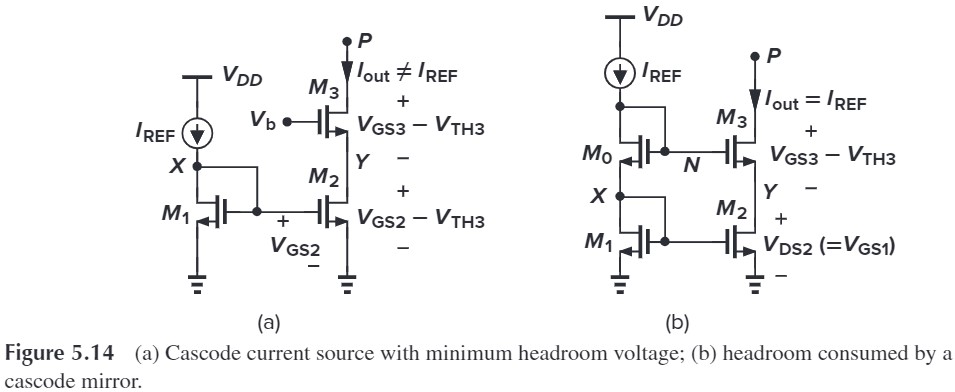
For simplicity, 忽略 body effect, 并假设 all of the transistors are identical. 那么,$P$ 处的最小电压为:
- (a) $V_P=(V_{GS3}-V_\tx{TH})+(V_{GS2}-V_\tx{TH})$
- (b) $V_P=V_N - V_\tx{TH}\(=V_{GS0}+V_{GS1}-V_\tx{TH}\)=(V_{GS0}-V_\tx{TH})+(V_{GS1}-V_\tx{TH})+V_\tx{TH}$
这两者的差异在于,(a) 中电压必须走 $Y$ 支路,从而必须有 $V_Y=V_{GS2}-V_\tx{TH}$;而 (b) 中电压可以走另一条路 $X$,从而 $V_X=V_{GS1}$,这样就少减了个 $V_\tx{TH}$,裕度就减少了。
那么我们为啥不用 (a) 呢?因为 (a) 不能保证 $M_1$, $M_2$ 的 $V_{DS}$ 相等,我们必须让 $V_b$ track $V_{GS3}+V_{DS2}$(即 $V_{GS3}+V_{DS1}=V_{GS3}+(V_{GS1}-V_\tx{TH})$)。那么有办法实现这一点吗?下面我们来讨论一下。
方法二
注意到 Fig. 5.14 (a) 中,我们要让 $V_X=V_Y=V_{GS2}-V_\tx{TH}$,即 $V_{DS1}=V_{GS2}-V_\tx{TH}$。However,Since $M_1$ is a diode-connected device, it appears impossible to expect a $V_{DS1}$ less than one threshold. 于是我们采用 Fig. 5.16(a) 中电路,令 $I_\tx{REF}R_1=V_\tx{TH}$,那么我们就有 $V_{DS1} = V_{GS1}-I_\tx{REF}R_1=V_{GS1}-V_\tx{TH}$,但由于 $R$ 可能会变,这种方式并不精确。
%20Use%20of%20IR%20drop%20to%20improve%20accuracy%20of%20current%20mirror,%20(b)%20generation%20of%20Vb,%20and%20(c)%20alternative%20generation%20of%20Vb.jpg)
那么我们可以换种方式,见 Fig. 5.18a,我们把电阻换成 MOS 管,那么,$V_{DS1}=V_{GS1}-V_{DS0}$,效果好像差不多诶!
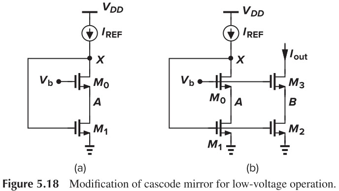
然后我们再将 $V_b$ 连在一起(Fig. 5.18),这么一来,$V_A=V_B=V_b-V_\tx{TH}$,就保证了 $V_{DS1}=V_{DS2}$
$V_b$ 的取值要保证 $M_0$,$M_1$ 都饱和,即:
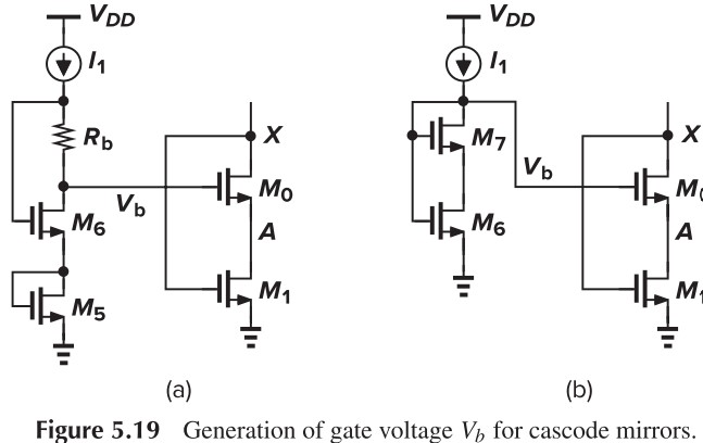
\[\begin{cases} V_b - V_\tx{TH0} \leq V_X = V_{GS1}\\ V_{GS1}-V_\tx{TH1}\leq V_A = V_b - V_{GS0} \end{cases}\\ \Downarrow\\ V_{GS0}+(V_{GS1}-V_\tx{TH1})\leq V_b \leq V_{GS1}+V_\tx{TH0}\]We can generate $V_b$ with the circuits in Fig. 5.19(具体分析咱就不说了)
Active Current Mirrors
Differential Pair with Passive Load
%20Differential%20pair%20with%20current-source%20load;%20(b)%20circuit%20for%20calculation%20of%20Gm;%20(c)%20circuit%20for%20calculation%20of%20Rout.jpg)
这个电路没什么好说的,用电流源当负载,其增益计算如下:
\[\begin{aligned} |A_v| &= G_m R_\tx{out}\\ G_m &= \frac{I_\tx{out}}{V_\tx{in}}= g_{m1}\frac{V_\tx{in}}{2} \Big/V_\tx{in}=\frac{g_{m1}}{2}\\ R_\tx{out} &= r_{O4} \Vert \left[ r_{O2}+(1+g_{m2}r_{O2})(r_{O1}\Vert \frac{1}{g_{m1}})\right]\\ &\approx r_{O4} \Vert 2r_{O2} \end{aligned}\]唯一要注意的是 $R_\tx{out}$ 的计算。另外说说这个电路的缺点:$M_1$ 那边的电流被浪费了,并且没有对增益作出贡献。
Differential Pair with Active Load
Five-transistor OTA 这个电路十分重要!!请好好学!
%20Concept%20of%20combining%20the%20drain%20currents%20of%20M1%20and%20M2,%20(b)%20realization%20of%20(a),%20and%20(c)%20response%20of%20the%20circuit%20to%20differential%20inputs.jpg)
首先我们从感性上看看这个电路是如何工作的。假设输入了正的差分电压,即 $V_\tx{in1} \uparrow$,这会导致 $I_{D1}\uparrow$,电流源会将这个电流按比例 copy 到输出,从而 $V_\tx{out}=I_{D1}(r_{O2}\Vert r_{O4})$ 会增大;同时,$V_\tx{in2}\downarrow$,$I_{D2}\downarrow$,从而共源输出 $V_\tx{out}=I_{D2}(r_{O2}\Vert r_{O4})$ 也会增大。这么一来,在两边作用下,增益为为 $g_m(r_{O2}\Vert r_{O4})$
Large-Signal Analysis
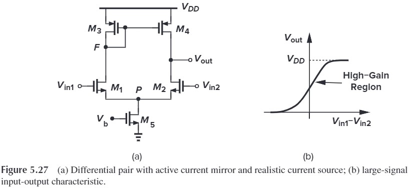
- 正常情况下,五管均应该饱和
- 若 $V_\tx{in1}\gg V_\tx{in2}$,那么 $M_1$ 关闭,那么 $M_3$ 也不会有电流,$M_3$ 要么是饱和要么关闭,而由于没有电流,所以只能是关闭,因此 $V_F=V_{DD}$。因此 $M_4$ 也关闭,从而 $V_\tx{out}=0$。此时 $M_2,M_5$ is in deep triode region
- 类似的,若 $V_\tx{in2}\gg V_\tx{in1}$,那么 $M_2$ 关闭,$I_{D2}=0$,从而 $M_4$ is in deep triode region,$V_\tx{out}=V_{DD}$。此时 $M_1,M_3,M_5$ 均饱和。
For $M_2$ to be saturated, $V_\tx{out}$ cannot be less than $V_\tx{in,CM}-V_\tx{TH}$. Thus, to allow maximum output swings, minimum CM level is given by $V_{GS1,2}+V_{DS5,\tx{min}}$
If $V_\tx{in1}=V_\tx{in2}$, the CM output is $V_\tx{out}=V_F=V_{DD}-\vert V_{GS3} \vert$
Small-Signal Analysis
Approximate Analysis
We simply use the lemma $\vert A_v \vert = G_m R_\tx{out}$ to calculate the gain.
For the calculation of $G_m$, consider Fig. 5.32. The current producted by $M_1$ is copied to $I_\tx{out}$ by current mirror. Therefore, $I_{D1}=\vert I_{D3}\vert = \vert I_{D4}\vert = g_{m1,2}V_\tx{in}/2$ and $I_{D2}=-g_{m1,2}V_\tx{in}/2$. yielding $I_\tx{out}=-g_{m1,2}V_\tx{in}$ and hence $\vert G_m \vert = g_{m1,2}$
%20Circuit%20for%20calculation%20of%20Gm;%20(b)%20circuit%20of%20(a)%20with%20node%20P%20grounded.jpg)
%20Circuit%20for%20calculating%20Rout;%20(b)%20substitution%20of%20a%20resistor%20for%20M1%20and%20M2.jpg)
To calculate $R_\tx{out}$, we use the circuit in Fig. 5.33. We replace $M_1,M_2$ with $R_{XY}=2r_{O1,2}$, and the current on it is
\[I_{1,2}=\frac{V_X}{2r_{O1,2}+(1/g_{m3})\Vert r_{O3}}\]We multiply this current by $(1/g_{m3})\vert r_{O3}$ to obtain the gate-source voltage of $M_4$ and then multiply the result by $g_{m4}$. It follows that
\[I_X = \frac{V_X}{2r_{O1,2}+(1/g_{m3})\Vert r_{O3}}\left[ 1+\left(\frac{1}{g_{m3}}\Vert r_{O3}\right)g_{m4} \right]+\frac{V_X}{r_{O4}}\]For $2r_{O1,2}\gg (1/g_{m3})\Vert r_{O3}$, we have
\[R_\tx{out} \approx r_{O2} \Vert r_{O4}\]The overall voltage gain is approximately equal to $\vert A_v \vert = G_m R_\tx{out} = g_{m1,2}(r_{O2}\Vert r_{O4})$
Exact Analysis
就是用小信号模型求解,此处仅给出结果:
\[\vert A_v \vert = g_{m1,2}(r_{O2}\Vert r_{O4}) \frac{2g_{m4}r_{O4}+1}{2(g_{m4}r_{O4}+1)}\]就是之前的结果乘上一个系数。