噪声的统计学性质
平均功率
尽管噪声是随机的,但有些统计性质是确定的。比如说:平均功率
\[\tx{average power} P_\tx{av} = \lim_{T\rightarrow \infty} \frac{1}{T} \int_{-T/2}^{+T/2} \frac{v^2(t)}{R_L} \dif t\\\](To be more rigorous, $v^2(t)$ should be replaced by $v(t)\cdot v^*(t)$)
有时候也直接简写为:
\[P_\tx{av} = \lim_{T\rightarrow \infty} \frac{1}{T} \int_{-T/2}^{+T/2} v^2(t) \dif t\]这样写的好处是,the actual power delivered to a load $R_L$ can be readily calculated as $P_\tx{av}/R_L$, and we can also define a root-mean-square (rms) voltage for noise as $\sqrt{P_\tx{av}}$
Noise Spectrum
Power spectral density (PSD) $S_x(f)$ shows how much power the signal carries at each frequency. $S_x(f)$ is defined as the average power carried by $x(t)$ in a one-hertz bandwidth around $f$,根据这个定义,$S_x(f)$ 的单位为 ${\rm V^2/Hz}$
白噪声 White spectum, also called white noise, displays the same value at all frequencies (or at the band of interest).
定理:If a signal with spectrum $S_x(f)$ is applied to a linear time-invariant system with transfer function $H(s)$, then the output spectrum is given by
\[S_Y(f)=S_x(f)\vert H(f) \vert^2\]之前我们学过频谱的范围是 $f\in(-\infty,+\infty)$,而实信号的频谱是反对称的,PSD 是对称的,所以我们可以将它画到正的。

定理:平均功率与功率频谱满足如下关系:
\[P_\tx{av} = \int_{-\infty}^{+\infty} S_x(f) \dif f\]Amplitude Distribution
Distribution of the amplitude, also called the “probability density function” (PDF), is defined as
\[p_x(x)\dif x = \tx{probability of } x<X<x+\dif x\]where $X$ is the measured value of $x(t)$ at some point in time.
常见的分布为高斯分布:$p_X(x)=\dfrac{1}{\sigma\sqrt{2\pi}} \exp \dfrac{-(x-m)^2}{2\sigma^2}$
Correlated and Uncorrelated Sources
我们考虑多个信号的平均功率:
\[\begin{aligned} P_\tx{av} &= \lim_{T\rightarrow \infty} \frac{1}{T} \int_{-T/2}^{+T/2} [x_1(t)+x_2(t)]^2 \dif t\\ &=\lim_{T\rightarrow \infty} \frac{1}{T} \int_{-T/2}^{+T/2} x_1^2(t) \dif t + \lim_{T\rightarrow \infty} \frac{1}{T} \int_{-T/2}^{+T/2} x_2^2(t) \dif t\\ &\quad + \lim_{T\rightarrow \infty} \frac{1}{T} \int_{-T/2}^{+T/2} 2x_1(t)x_2(t) \dif t\\ &= P_\tx{av1}+P_\tx{av2}+\lim_{T\rightarrow \infty} \frac{1}{T} \int_{-T/2}^{+T/2} 2x_1(t)x_2(t) \dif t \end{aligned}\]第三项称为 correlation。如果 correlation 为 0,那么就说这两个噪声是不相关的 uncorrelated,否则为 correlated(但我们后面一般都是先判断是否相关,再决定这项是是否为 0)
如果两个不相关,那么 $P_\tx{av}=P_\tx{av1}+P_\tx{av2}$
%20Uncorrelated%20noise%20and%20(b)%20correlated%20noise%20generated%20in%20a%20stadium.jpg)
Signal-to-Noise Ratio
信噪比 SNR 定义如下:
\[\tx{SNR} = \frac{P_\tx{sig}}{P_\tx{noise}}\\ 或 =10\log (P_\tx{sig}/P_\tx{noise})\]Noise Analysis Procedure
- Identify the sources of noise (e.g., resistors and transistors) and write down the spectrum of each
- Find the transfer function from each noise source to the output (as if the source were a deterministicsignal)
- Utilize the theorem $S_Y(f)=S_x(f)\vert H(f)\vert^2$ to calculate the output noise spectrum contributed by each noise source. (The input signal is set to zero.)
- Add all of the output spectra, paying attention to correlated and uncorrelated sources.
最终得到输出的噪声频谱。
Types of Noise
- electronic noise
- thermal noise
- flicker noise (1/f noise)
- environmantal noise
Thermal Noise
Resistor Thermal Noise
- 产生原因:The random motion of electrons in a conductor
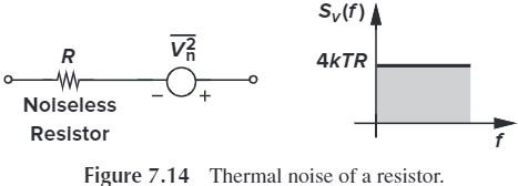
- one-sided spectral density:$S_v(f)=4kTR, f\geq 0$
- $k=1.38\times10^{-23}$ J/K is the Boltmann constant
- 模型:
- 无噪声的电阻与一个 $\overline{V_n^2}=4kTR$ 的电压源串联
- 无噪声的电阻与一个 $\overline{I_n^2}=4kT/R$ 的电流源并联

计算 Fig. 7.15 在输出端的噪声频谱与噪声功率。

把噪声看作输入,则传输函数为:
$$
\frac{V_\tx{out}}{V_R}(s) = \frac{1}{RCS+1}
$$
那么频谱为:
$$
\begin{aligned}
S_\tx{out}(f) &= S_v(f)\left| \frac{V_\tx{out}}{V_R}(j\omega)\right|^2\\
&=4kTR\frac{1}{4\pi^2 R^2 C^2 f^2 + 1}
\end{aligned}
$$

对频谱积分就得到噪声功率
$$ \begin{aligned} P_{n,\tx{out}} &= \int_0^{\infty} \frac{4kTR}{4\pi^2 R^2 C^2 f^2 + 1} \dif f\\ &=\frac{2kT}{\pi C} \int_0^\infty \frac{1}{x^2 + 1} \dif x\\ &=\frac{2kT}{\pi C} \tan^{-1} x\big\vert_0^\infty\\ &=\frac{kT}{C} \end{aligned} $$ 这说明输出的噪声功率与电阻无关。因为当电阻增大时,虽然噪声也会增大,但传输函数减小(即带宽减小),最终噪声功率并没有变。
MOSFETs
- 产生原因:the noise generated in the channel
- 模型:
- 在 SD 两边并联上电流源 $\overline{I_n^2} = 4kT\gamma g_m$
- 在 $r_O$ 上串联上电压源 $\overline{V_n^2}=(4kT\gamma g_m)r_O^2$
- 注:
- 式中的 $\gamma$ 不是体效应的 $\gamma$。对于长沟道;$\gamma=2/3$,对于短沟道,这个值会变大。并且还与源漏电压有一定关系。一般我们认为 $\gamma\approx 1$
- $r_O$ 是等效电阻,不产生噪声

%20Layout%20of%20a%20MOSFET%20indicating%20the%20terminal%20resistances;%20(b)%20circuit%20model;%20(c)%20distributed%20gate%20resistance.jpg)
此外,欧姆接触、材料电阻也会产生一定噪声,如 Fig. 7.22 所示,但注意,$R_1=R_G/3$,证明如下。
我们将 Fig. 7.21a 转化为 c 中的结构。我们不妨将晶体管从左到右标号为 $1\sim n$,则对于第 $i$ 个晶体管,它的噪声电压由左边的电阻产生,具体值为 $\overline{V_{n,i}}=i\cdot\sqrt{4kT\dfrac{R_G}{n}}$,经过放大后在漏级产生的电流为 $\dfrac{g_m i}{n}\sqrt{4kT\dfrac{R_G}{n}}$
如果将电流功率相加,并取极限,则有:
$$
\begin{aligned}
\overline{I_n^2} &= \lim_{n\rightarrow \infty}\sum_{i=1}^n \dfrac{g_m^2 i^2}{n^2}4kT\dfrac{R_G}{n}\\
&= g_m^2 \cdot 4kTR_G \lim_{n\rightarrow\infty} \sum_{i=1}^n \frac{i^2}{n^3}\\
&= g_m^2 \cdot 4kTR_G \cdot \lim_{n \rightarrow \infty} \frac{n(n+1)(2n+1)}{6n^3}\\
&= g_m^2 \cdot 4kTR_G \cdot \frac{1}{3}
\end{aligned}
$$
这等效于一个 $\dfrac{R_D}{3}$ 电阻在栅产生的噪声。
Filcker Noise
闪烁噪声 Filcker Noise(也叫 $1/f$ noise)
- 产生原因:沟道与 ${\rm SiO_2}$ 边界表面的悬挂键断裂时,导致漏极电流有噪声
- 模型:$\overline{V_n^2}=\dfrac{K}{C_\tx{ox}WL}\cdot \dfrac{1}{f}$
- $K$ 取决于工艺,数量级在 $10^{-25} {\rm V^2F}$
- $C_\tx{ox}$ 也取决于工艺
我们可以对比一下晶体管中的 Filcker Noise 和 Thermal Noise,假设这两个功率相等:
\[4kT\gamma g_m = \frac{K}{C_\tx{ox}WL}\cdot\frac{1}{f}\cdot g_m^2\\ \Rightarrow f_C=\frac{K}{\gamma C_\tx{ox} WL} g_m \frac{1}{4kT}\]$f_C$ 称为 corner frequency. 虽然这个值也与 $g_m$ 有关,但我们可以近似认为它只与 $L$ 有关,nanomoter transistors 中大概是 10~50 MHz。当高于该频率时,可以忽略 fliker noise.

噪声在电路中的表示
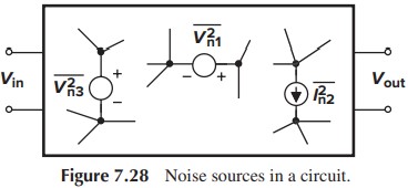
为了衡量电路中总的噪声,我们有两种方法。一种叫 output noise,与我们前面的步骤一样,即假设输入为 0,然后计算噪声在输出端的平均功率。另一种叫 input-referred noise,即假设电路无噪声,在输出噪声不变的情况下,计算输入端需要输入多大功率的噪声。
为什么需要输入噪声?假设 CS stage 的 output noise 为 $\overline{V_{n,\tx{out}}}$,如果我们再串联一个无噪声的放大器(Fig. 7.30),那么输出噪声为 $A_v^2 \overline{V_{n,\tx{out}}}$. 如果放大器的增益不同,就会导致明明噪声源是一样的,但输出噪声却不一样。

而输入噪声就不会出现上述问题。因为 $\overline{V_{n,\tx{in}}}=\dfrac{\overline{V_{n,\tx{out}}}}{A_v^2}$,排除了增益的影响。(这里也可以说是考虑了增益的影响,因为增益越大,那么信号经放大后的功率就越大,相比之下噪声就越小,SNR 越高)
求下图电路的输入、输出噪声
%20CS%20stage;%20(b)%20circuit%20including%20noise%20sources.jpg)
MOS 管包括热噪声与 1/f 噪声,电阻有热噪声
$$
\overline{I_{n,\tx{th}}^2}=4kT\gamma g_m\\
\overline{I_{n,1/f}^2}=Kg_m^2/(C_\tx{ox}WLf)\\
\overline{I_{n,R_D}^2}=4kT/R_D
$$
从而在输出端,有(注意,我们这里算的是功率,所以不考虑方向):
$$
\begin{aligned}
\overline{V_{n,\tx{out}}^2}&=(\overline{I_{n,\tx{th}}^2}+\overline{I_{n,1/f}^2}+\overline{I_{n,R_D}^2})R_D^2\\
&= \left( 4kT\gamma g_m + Kg_m^2/(C_\tx{ox}WLf) + \frac{4kT}{R_D}\right) R_D^2
\end{aligned}
$$
在输入端,有:
$$
\begin{aligned}
\overline{V_{n,\tx{in}}^2}&=\frac{\overline{V_{n,\tx{out}}^2}}{A_v^2}\\
&=4kT \left( \frac{\gamma}{g_m}+\frac{1}{g_m^2 R_D} \right)+\frac{K}{C_\tx{ox}WL} \frac{1}{f}
\end{aligned}
$$
但光有噪声电压源不够,我们还需要噪声电流源才行。为什么?如果不考虑上一级,那么确实只需要噪声电压就行了。但如果考虑上一级的电阻,那么咱的噪声电压可鞥会被分压,导致实际输入的噪声电压减小。所以,完整的模型如下:

- 求输入噪声电压功率(Fig. 7.34a):设上一级阻抗为 $0$,求出输出电压功率,然后再求输入电压功率
- 求输入噪声电流功率(Fig. 7.34b):设上一级阻抗为 $\infty$,求出输出电压功率,然后再求输入电流功率
%20voltage%20and%20(b)%20current.jpg)

我们来看看这个模型在电路中的表现。考虑 Fig. 7.36,在 $X$ 处的电压为:
\[V_{n,X} = \frac{Z_\tx{in}}{Z_\tx{in}+Z_S}V_{n,\tx{in}}+\frac{Z_\tx{in}Z_S}{Z_\tx{in}+Z_S}I_{n,\tx{in}}\]假设输出噪声为 $V_{n,\tx{out}}$,那么,我们容易求得 $V_{n,\tx{in}}=\frac{V_{n,\tx{out}}}{A_v}$,$I_{n,\tx{in}}=\frac{V_{n,\tx{out}}}{A_v Z_\tx{in}}$,代入上式,有:
\[\begin{aligned} V_{n,X} &= \frac{Z_\tx{in}}{Z_\tx{in}+Z_S} \frac{V_{n,\tx{out}}}{A_v} + \frac{Z_\tx{in}Z_S}{Z_\tx{in}+Z_S} \frac{V_{n,\tx{out}}}{A_v Z_\tx{in}}\\ &= \frac{V_{n,\tx{out}}}{A_v}\\ \Rightarrow &V_{n, \tx{out}} = A_v V_{n,X} = V_{n,\tx{out}} \end{aligned}\]从上面的计算中可以看到,虽然有两个源,但并不会导致噪声加倍。
在某些情况下,我们可以忽略 $V_{n,\tx{in}}$ 或 $I_{n,\tx{in}}$。因为 $V_{n,X}$ 可以改写为 $\frac{Z_\tx{in}}{Z_\tx{in}+Z_S}\left( V_{n,\tx{in}}+Z_S I_{n,\tx{in}} \right)$,如果 $V_{n,\tx{in}} \gg Z_S I_{n,\tx{in}}$,那么我们就可以忽略 $I_{n,\tx{in}}$,换句话说:
\[\tx{if }\vert Z_S \vert^2 \ll \frac{\overline{V_{n,\tx{in}}^2}}{\overline{I_{n,\tx{in}}^2}}\\ \tx{then the input-referred noise current can be neglected}\]单极放大器的噪声
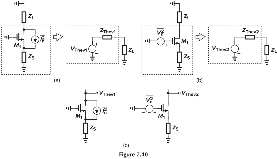
辅助定理:Fig. 7.39 (a) and (b) are equivalent at low frequencies when $\overline{V_n^2}=\dfrac{\overline{I_n^2}}{g_m^2}$
简单证明:(这里我用 (a)(b) 来证明,书本上用的是 (c)(d),结论是一样的)
对于 (a):KVL
\[\overline{V_{n,\tx{out}}} = -\frac{\overline{V_{n,\tx{out}}}}{Z_L}Z_S+\left( -\frac{\overline{V_{n,\tx{out}}}}{Z_L}-\frac{\overline{V_{n,\tx{out}}}}{Z_L} Z_S(g_m+g_{mb})- \overline{I_{n}}\right)\cdot r_O\\ \Rightarrow \overline{V_{n,\tx{out}}} = \frac{-r_OZ_L\overline{I_n}}{Z_L+Z_S+r_O+(g_m+g_{mb})Z_Sr_O}\]对于 (b):利用 $\overline{V_n^2}$ 求
\[\overline{V_{n,\tx{out}}}=\overline{V_{n}} A_v\\ A_v = \frac{-g_mr_OZ_L}{Z_L+Z_S+r_O+(g_m+g_{mb})Z_Sr_O}\\ \Rightarrow \overline{V_{n,\tx{out}}} = \frac{-r_OZ_L\overline{I_n}}{Z_L+Z_S+r_O+(g_m+g_{mb})Z_Sr_O}\]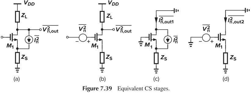
注意哦,我们这里并没有说明 $\overline{I_n^2}$ 的来源,也就是说上面这个定理也可以用于电阻的噪声哦。
加深理解:请用戴维宁等效来证明上面的辅助定理
CS Stage
在前面的例题中求过了 $\overline{V_{n,\tx{in}}^2}$,得到的结果是:
\[\overline{V_{n,\tx{in}}^2} = 4kT \left( \frac{\gamma}{g_m}+\frac{1}{g_m^2 R_D} \right)+\frac{K}{C_\tx{ox}WL} \frac{1}{f}\]我们来试着利用辅助定理来重新求一下。我们将下面几个噪声等效到输入端:
\[\begin{cases} \overline{I_{n,\tx{th}}^2}=4kT\gamma g_m\\ \overline{I_{n,1/f}^2}=Kg_m^2/(C_\tx{ox}WLf)\\ \overline{I_{n,R_D}^2}=4kT/R_D \end{cases}\\ \Downarrow \tx{divided by } g_m^2\\ \begin{cases} \overline{V_\tx{Thev1}^2}=4kT\gamma/g_m\\ \overline{V_\tx{Thev2}^2}=K/(C_\tx{ox}WLf)\\ \overline{V_\tx{Thev3}^2}=4kT/(g_m^2 R_D) \end{cases}\] \[\overline{V_{n,\tx{in}}^2} = \overline{V_\tx{Thev1}^2}+\overline{V_\tx{Thev2}^2}+\overline{V_\tx{Thev3}^2}\]有趣的是,1/f 噪声等效到输入端后,和原本的 $\overline{V_{n,1/f}^2}$ 是一样的。
显然,这样求比之前的方法快多了。另外,由于输入阻抗无穷大,所以 input-referred current 为 0.
因此,如果要减小 CS stage 的噪声,那么就要增大 $g_m$,增大 $R_D$(有趣的是,这也是增大增益的方法,看来增大增益=减小噪声),但注意,这有个前提:MOS 要用作 amplifier 而不是 current source。书中列举了下面的例子来说明:
Calculate the input-referred thermal noise voltage of the amplifier shown in Fig. 7.42(a)
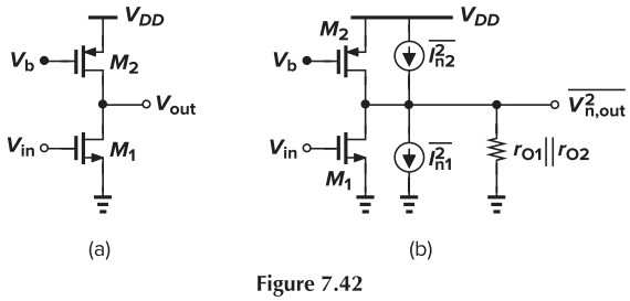
the thermal noise of $M_1$ and $M_2$ are uncorrelated, therefore we write
$$
\overline{V_{n,\tx{out}}^2} = 4kT(\gamma g_{m1}+\gamma g_{m2})(r_{O1}\Vert r_{O2})^2\\
\begin{aligned}
\overline{V_{n,\tx{in}}^2} &= \frac{\overline{V_{n,\tx{out}}^2}}{g_{m1}^2(r_{O1}\Vert r_{O2})^2}\\
&= 4kT \gamma \left( \frac{1}{g_{m1}}+\frac{g_{m2}}{g_{m1}^2} \right)
\end{aligned}
$$
The equation above reveals the dependence of $\overline{V_{n,\tx{in}}^2}$ upon $g_{m1}$ and $g_{m2}$, confirming that $g_{m2}$ must be minimized because $M_2$ serves as a current source rather than a transconductor.
也就是说,如果 MOS 用于放大电压,那么 $g_m$ 大才能减小噪声;如果 MOS 用于当作电流源,那么 $g_m$ 小才能减小噪声。
最后我们来说一下其他减小噪声的方法:
- 增大 $g_{m1}$,即
- 增大 $I_D$——trade-off: greater power dissipation
- 增大 $W$——trade-off: larger input and output capacitance
- 增大 $R_D$——trade-off: limiting the voltage headroom and lowering the speed
- 增大 $WL$,同时保持 $W/L$ 不变——trade-off: the device capacitances increase
CG Stage
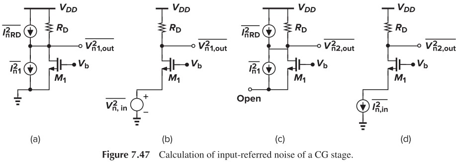
容易算出,输入接地时,输出噪声功率为:$\left( 4kT\gamma g_m + \dfrac{4KT}{R_D} \right) R_D^2$,从而输入噪声电压:
\[\left( 4kT\gamma g_m + \dfrac{4KT}{R_D} \right) R_D^2 = \overline{V_{n,\tx{in}}^2} (g_m+g_{mb})^2 R_D^2\\ \Rightarrow \overline{V_{n,\tx{in}}^2} = \dfrac{4kT(\gamma g_m+1/R_D)}{(g_m+g_{mb})^2}\]而输入开路时,注意到源端处有:$I_{n1}+I_{S1}=0$,从而漏端处有:$I_{n1}+I_{D1}=0$,也就是说,$I_{n1}$ 不会流过 $R_D$!从而输出噪声功率为 $\overline{V_{n,\tx{out}}}=4kTR_D$,从而输入噪声功率为:
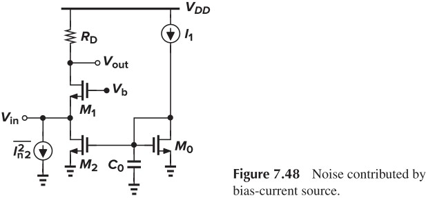
\[\overline{I_{n,\tx{in}}^2} = \frac{4kT}{R_D}=\overline{I_{n,R_D}^2}\]上式说明,输入噪声电流就等于电阻的噪声电流,这是因为这个电路不能放大电流,输入的电流直接就反应到了输出。假如我们用一个电流镜提供偏置(Fig. 7.48),那么 $M_2$ 的噪声电流也会直接反应到输出。
下面我们来考虑 Filker Noise.
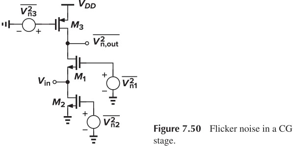
With the input shorted to ground, we have
\[\overline{V_{n1,\tx{out}}^2} = \frac{1}{C_\tx{ox} f} \left[ \frac{g_{m1}^2K_N}{(WL)_1}+\frac{g_{m3}^2K_P}{(WL)_3} \right] (r_{O1}\Vert r_{O3})^2\\ A_v = (g_{m1}+g_{mb1})(r_{O1}\Vert r_{O3})\\ \Rightarrow \overline{V_{n,\tx{in}}^2} = \frac{1}{C_\tx{ox} f} \left[ \frac{g_{m1}^2K_N}{(WL)_1}+\frac{g_{m3}^2K_P}{(WL)_3} \right] \frac{1}{(g_{m1}+g_{mb1})^2}\]With the input open, we have
\[\overline{V_{n2,\tx{out}}^2} = \frac{1}{C_\tx{ox} f} \left[ \frac{g_{m2}^2K_N}{(WL)_2}+\frac{g_{m3}^2K_P}{(WL)_3} \right] R_\tx{out}^2\\ \overline{I_{n,\tx{in}}^2} = \frac{1}{C_\tx{ox} f} \left[ \frac{g_{m2}^2K_N}{(WL)_2}+\frac{g_{m3}^2K_P}{(WL)_3} \right]\]此处忽略 $M_1$ 的噪声,因为根据前面 cascode 的 golden rule,$M_1$ 的 $V_D = g_{m1}r_{o1} V_S$,会将下面的噪声放大。
把 1/f 噪声与前面的热噪声相加,就得到总的噪声。
Source Followers
%20Source%20follower;%20(b)%20circuit%20including%20noise%20sources.jpg)
由于这个电路的输入阻抗很大,所以只需计算 $\overline{V_{n,\tx{in}}^2}$。其中,$M_1$ 的噪声可以直接利用辅助定理折算到输入端,而 $M_2$ 的噪声计算如下:
\[\overline{V_{n,\tx{out}}^2} = \overline{I_{n2}^2} \left( \frac{1}{g_{m1}}\Vert \frac{1}{g_{mb1}} \Vert r_{O1} \Vert r_{O2} \right)^2\\ A_v = \frac{g_{m1}}{g_{m1}+g_{mb1} + 1/r_{O1} + 1/r_{O2}}\\ \Rightarrow \overline{V_{n2,\tx{in}}^2}= \frac{\overline{V_{n,\tx{out}}^2}}{A_v^2}=4kT\gamma \frac{g_{m2}}{g_{m1}^2}\]从而总的热噪声为:
\[\begin{aligned} \overline{V_{n,\tx{in}}^2} &= \overline{V_{n1,\tx{in}^2}}+\overline{V_{n2,\tx{in}^2}}\\ &=4kT\gamma \left( \frac{1}{g_{m1}}+\frac{g_{m2}}{g_{m1}^2} \right) \end{aligned}\]补充一种更好的计算方法:注意到无论是 M1 还是 M2,它们的增益都是 $g_m R_\tx{out}$。所以我们可以先将 M1、M2 噪声等效到各自的栅端,假设等效后分别为 $\overline{V_{n,1}^2}$、$\overline{V_{n,2}^2}$,则输出噪声为:
\[\overline{V_{n,\tx{out}}^2}=\overline{V_{n,1}^2}(g_{m1}R_\tx{out})^2+\overline{V_{n,2}^2}(g_{m2}R_\tx{out})^2\]然后再除以实际增益(即 $g_{m1}R_\tx{out}$),就能得到输入噪声为:
\[\overline{V_{n,\tx{in}}^2} = \overline{V_{n,1}^2}+\overline{V_{n,2}^2} \frac{g_{m2}^2}{g_{m1}^2}\]Cascode Stage
根据前面 CS Stage 和 CG Stage,我们易求出:
\[\begin{aligned} \overline{V_{n,\tx{in}}^2} &= \frac{\overline{I_{n,\tx{out}}^2}}{g_{m1}^2}\\ &= 4kT \left( \frac{\gamma}{g_{m1}}+\frac{1}{g_{m1}^2R_D} \right) \end{aligned}\]%20Cascode%20stage;%20(b)%20noise%20of%20M2%20modeled%20by%20a%20current%20source;%20(c)%20noise%20of%20M2%20modeled%20by%20a%20voltage%20source.jpg)
电流镜的噪声
差分放大电路的噪声
%20Differential%20pair;%20(b)%20circuit%20including%20input-referred%20noise%20sources.jpg)
We can model the overall noise as depicted in Fig. 7.55(b). For low-frequency operation, $\overline{I_{n,\tx{in}}^2}$ is negligible.
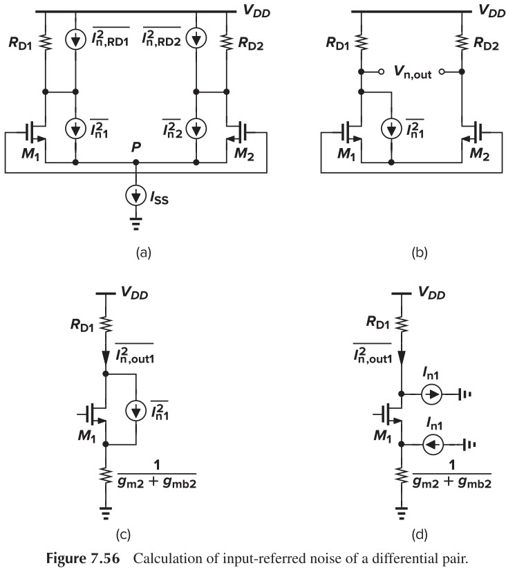
To calculate the thermal component of $\overline{V_{n,\tx{in}}^2}$, we first obtain the total output noise with the inputs shorted together (Fig. 7.56a). Since the noise sources in the circuit are uncorrelated, we simply derive the effect of each source individually (Fig. 7.56b). the contribution of In1 is obtained by first reducing the circuit to that in (Fig. 7.56c). With neglecting channel-length modulation, we can prove that half of $I_{n1}$ flows through $R_{D1}$ and the other half through $M_2$ and $R_{D2}$ (这个我是真不知道怎么证明😥,目前唯一的解释就是 $M_1$ 的源端看进去的电阻也等于 $1/(g_{m2}+g_{mb2})$,这样一半电流往下,另一半则流过 $M_1$).
Thus, the differential output noise due to M1 is equal to
\[V_{n,\tx{out}}\Big\vert_{M1}=\frac{I_{n1}}{2} R_{D1}+\frac{I_{n1}}{2} R_{D2}\]为了简化计算,我们设 $R_{D1}=R_{D2}=R_D$,那么:
\[\overline{V_{n,\tx{out}}^2}\Big\vert_{M1}=\overline{I_{n1}^2}R_D^2\]同理,
\[\overline{V_{n,\tx{out}}^2}\Big\vert_{M2}=\overline{I_{n2}^2}R_D^2\]从而
\[\begin{aligned} \overline{V_{n,\tx{out}}^2} &= \left( \overline{I_{n1}^2}+\overline{I_{n2}^2} \right)R_D^2 + 2(4kTR_D)\\ &=8kT(\gamma g_m R_D^2+R_D) \end{aligned}\]除以增益 $g_m R_D$,我们有
\[\overline{V_{n,\tx{in}}^2}=8kT \left( \frac{\gamma}{g_m}+\frac{1}{g_m^2 R_D} \right)\]可见,这是 CS stage 噪声的两倍,即使我们考虑上 1/f 噪声,这也成立。顺便,考虑上 1/f 噪声的输入噪声如下:
\[\overline{V_{n,\tx{in}}^2}=8kT \left( \frac{\gamma}{g_m}+\frac{1}{g_m^2 R_D} \right)+\frac{2K}{C_\tx{ox}WL}\frac{1}{f}\]下面来考虑一下偏置电流源的噪声。当没有输入时,噪声电流会平分到两边,最终不影响差分输出;当有输入时,有:
\[\begin{aligned} \Delta I_{D1}-\Delta I_{D2} &= g_m \Delta V_\tx{in}\\ &= \sqrt{2\mu_n C_\tx{ox} \frac{W}{L}\left( \frac{I_{SS}+I_n}{2} \right)} \Delta V_\tx{in}\\ &\approx \sqrt{2\mu_n C_\tx{ox} \frac{W}{L} \frac{I_{SS}}{2}} \Delta V_\tx{in} \left( 1+\frac{I_n}{2 I_{SS}} \right) \Delta V_\tx{in}\\ &=g_{m0} \left( 1+\frac{I_n}{2 I_{SS}} \right) \Delta V_\tx{in} \end{aligned}\]说明当有差分输入时,噪声电流就会不平均地分配到两边,在输出产生噪声。(这个效应一般可以忽略)
最后我们来分析一下五管 OTA 的噪声。
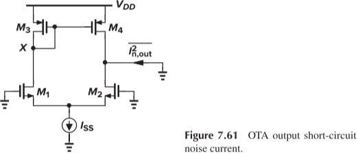
首先对于 $M_1,M_2$ 的噪声,直接用辅助定理就能得到输入噪声电压。下面我们重点讨论 $M_3,M_4$ 的噪声。
- 对于 $M_3$,它的噪声电流主要流经自己(即 $1/g_{m3}$),然后产生噪声电压 $4kT\gamma/g_{m3}$,再通过 $M_4$ 放大,得到输出噪声电流 $4kT \gamma g_{m4}^2 / g_{m3}$
- $M_4$ 的噪声电流直接流到输出端,等于 $4kT \gamma g_{m4}$
如果 $g_{m3}=g_{m4}=g_{m3,4}$,那么 $M_3,M_4$ 的输出噪声电流为 $4kT\cdot 2g_{m3,4}$,除以整个电路的跨导 $g_{m1,2}$,就得到输入噪声电压 $4kT\gamma \cdot 2g_{m3,4}/g_{m1,2}^2$
从而总的输入噪声电压为:
\[\overline{V_{n,\tx{in}}^2} = 8kT\gamma \left(\frac{1}{g_{m1,2}}+\frac{g_{m3,4}}{g_{m1,2}^2}\right)\]Noise Bandwith
噪声带宽 $B_n$ 定义如下:
\[V_0^2 \cdot B_n = \int_0^\infty \overline{V_{n,\tx{out}}^2} \dif f\]%20Output%20noise%20spectrum%20of%20a%20circuit;%20(b)%20concept%20of%20noise%20bandwidth.jpg)