Source Follower
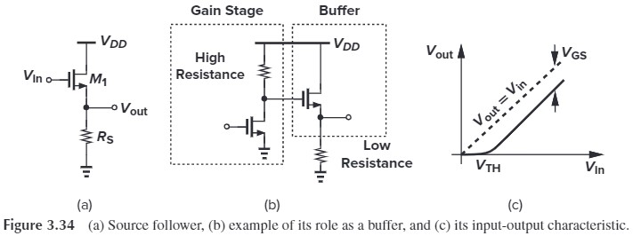
common-source stage requires a large load impedance to achieve a high voltage gain, if the load is low-impedance, we need a source follower be placed after the amplifier to act as a buffer.

From Fig. 3.35, we have (apply KVL to output)
\[V_\tx{out} = (g_m V_1 + g_{mb} V_{bs})R_S\\ \tx{where } \begin{aligned} V_1 &= V_\tx{in}-V_\tx{out}\\ V_{bs} &= -V_\tx{out} \end{aligned}\]整理后:
\[V_\tx{out} = (g_m V_\tx{in} - g_m V_\tx{out}-g_{mb}V_\tx{out})R_S\\ A_v=\frac{V_\tx{out}}{V_\tx{in}}=\frac{g_m R_S}{1+(g_m+g_{mb})R_S}\\ =\frac{g_m}{1/R_S+g_m+g_{mb}}\]我们也可以用饱和区 $I_D$ 与 $V_{GS}$ 的关系式来求:
\[\frac{1}{2}\mu_n C_{ox}\frac{W}{L}(V_\tx{in}-V_\tx{out}-V_\tx{TH})^2 R_S = V_\tx{out}\]这个过程比较复杂,一堆微分,咱就不写了。有兴趣的同学自行点开下面的推导。
利用 $I_D$ 与 $V_{GS}$ 的关系式求 $A_v$
哈哈,上当了吧!如果将 $A_v$ 改写为:
\[A_v=\dfrac{R_S}{1/g_m+(1+g_{mb}/g_m)R_S}\\ \approx \dfrac{R_S}{(1+g_{mb}/g_m)R_S}\\ \approx \dfrac{1}{1+\eta}\]考虑到 $\eta$ 随 $V_\tx{in}$ 增大而减小(为什么?因为 $V_\tx{in}$ 增大会导致 $V_{SB}$ 增大),所以我们有图 Fig. 3.36

为了提高线性性,我们可以把 $R_S$ 替换为一个电流源:

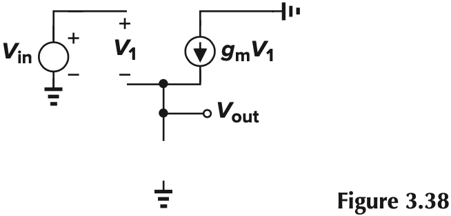
这样的话就能增大电阻,我们可以近似看作短路,这样的话,从 Fig. 3.38 可知,$g_mV_1=0$,即 $V_1=0$,这样 $V_\tx{out}=V_\tx{in}$
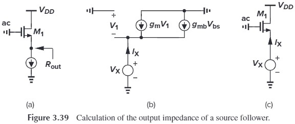
如果我们考虑上体效应(Fig. 3.39),那么相应的输出电阻为:
\[I_X-g_m V_X-g_{mb}V_X=0\\ R_\tx{out}=\frac {1}{g_m+g_{mb}}=\frac{1}{g_m}\Vert \frac{1}{g_{mb}}\]是不是和前面说的 diode-connected MOS 很像!!这里再次验证了从源端看进去的电阻为 $\frac{1}{g_m}\Vert \frac{1}{g_{mb}}$(再次强调,前提是不考虑 $r_O$)
书中还列举了其他方法计算 $V_\tx{out}$,这里就不介绍了。我们可以直接写出 $A_v$(简单地将之前的 $R_S$ 设为无穷大):
\[\begin{aligned} A_v &= g_m R_\tx{out}\\ &=\frac{g_m}{g_m+g_{mb}}\\ &= \frac{1}{1+\eta} \end{aligned}\]最后我们考虑一下带负载的情况。
%20Source%20follower%20driving%20load%20resistance;%20(b)%20small-signal%20equivalent%20circuit;%20(c)%20simplified%20model.png)
注意到小信号模型中,可以用等效电阻 $R_\tx{eq}=(1/g_{mb})\Vert r_{O1} \Vert r_{O2} \Vert R_L$ 简化为 Fig. 3.42(a) 的形式,从而输出为:
\[\begin{aligned} A_v &= \frac{R_\tx{eq}}{R_\tx{eq}+\dfrac{1}{g_m}} \\ &= \frac{g_m}{g_m + \dfrac{1}{R_\tx{eq}}} \end{aligned} \tag{3.96}\]最后我们来说一下 Source Follower 的缺点,Source followers exhibit a high input impedance and a moderate output impedance, but at the cost of two drawbacks:
- nonlinearity
- The nonlinear dependence of $V_\tx{TH}$ upon the source potential
- In submicron technologies, $r_O$ of the transistor also changes substantially with $V_{DS}$ (Chapter 14)
- body effect (PFETs’ body effect can be eliminated by tying bulk to souce)
- voltage headroom limitation
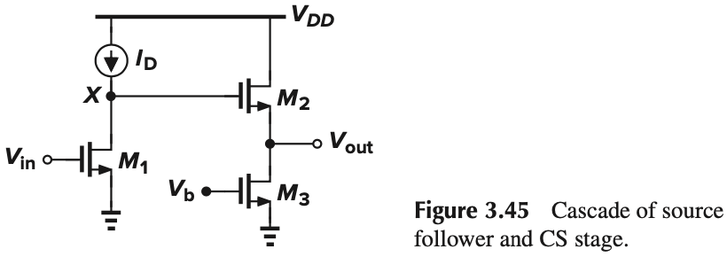
- Source followers shift the dc level of the signal by $V_{GS}$, consider the example in Figure 3.45
- Without the source follower, the minimum value of $V_X$ is $V_{GS1}-V_\tx{TH1}$
- With the source follower, the minimum value of $V_X$ is $V_{GS2}+(V_{GS1}-V_\tx{TH1})$
Summary
\[A_v = \frac{g_m}{g_m+g_{mb}+\dfrac{1}{r_O}+\dfrac{1}{R_S}+\dfrac{1}{R_L}}\]我们可以这样记忆:分子和之前一样是 $g_m$,分母是 $V_\tx{out}$ 上下所有 电导 的并联(即 $G_\tx{out}$)。另外,分母就是输出导抗(可以看出输出阻抗很小)
挑战:写出下面电路的 $A_v$
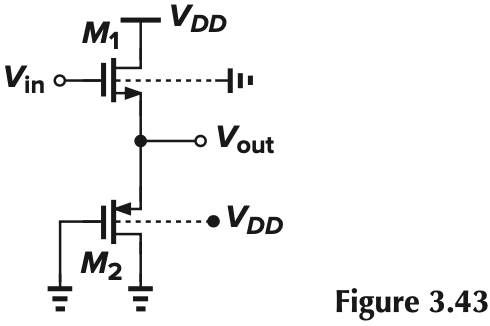
根据上面的总结,我们可以轻松写出:
$$
A_v = \frac{g_{m1}}{g_{m1}+g_{m2}+g_{mb2}+1/r_{O2}+1/r_{O1}}
$$