Cascode Stage
如果将两个 MOS 管按 Fig. 3.59 那样连起来,就是 cascode(表示 cascade triodes)。$M_1$ 受 $V_\tx{in}$ 调控产生电流,流经 $M_2$ 后产生 $V_\tx{out}$
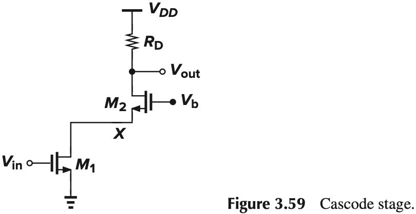
我们可以利用 CS stage 和 CG stage 的公式简略分析一下。假设两管都饱和,并且 $\lambda=\gamma=0$,那么:
- 对 $M_1$ 来说,负载是从 $M_2$ 源端看进去的电阻,故 $A_{v1}=-\dfrac{g_{m1}}{g_{m2}}$
- 对 $M_2$ 来说,$A_{v2}=g_{m1}R_D$
从而总的增益为:$A_v = A_{v1}A_{v2}=-g_{m1}R_D$,这个结果和 CS stage 是一样的(Fig. 3.60b)
%20an%20input%20device%20and%20(b)%20a%20cascode%20device.png)
注意到如果 $M_1,M_2$ 上的电流相等,那么它们的偏置必须满足一定的要求,并且输出幅度也会受偏置影响,具体分析如下:
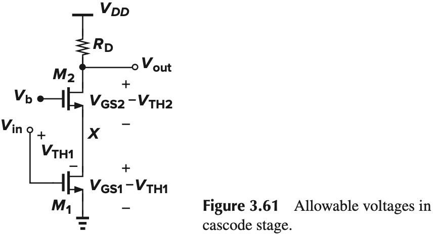
- 两管工作在饱和区:
- $V_\tx{in}>V_\tx{TH1}$ 且 $V_\tx{in}-V_\tx{TH1} \leq V_X$
- $V_b-V_X>V_\tx{TH2}$ 且 $V_b-V_\tx{TH2} \leq V_\tx{out}$
- 电压间满足一定关系:
- $V_X=V_b-V_{GS2}$
- $V_\tx{in}=V_{GS1}$
从而:
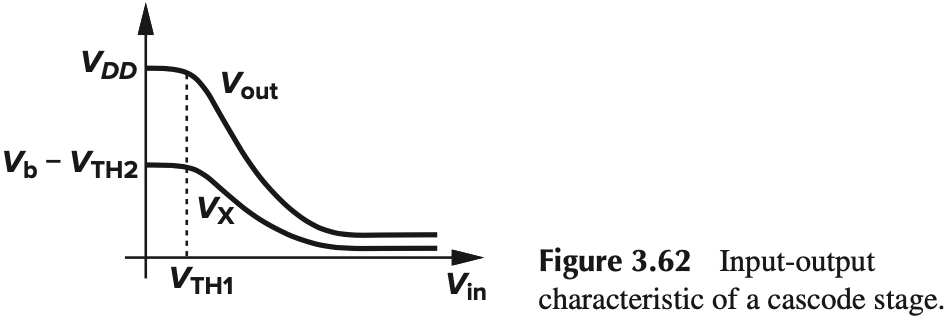
\[\begin{aligned} V_\tx{out} &\geq V_\tx{in} - V_\tx{TH1}+V_{GS2}-V_\tx{TH2}\\ &=(V_{GS1}-V_\tx{TH1})+(V_{GS2}-V_\tx{TH2}) \end{aligned}\]说明输出电压的下限是两管 overdrive voltage 之和。
以上只是饱和区的情况,完整的 large-sianl behavior 如下(分析过程略):
小信号模型如下:
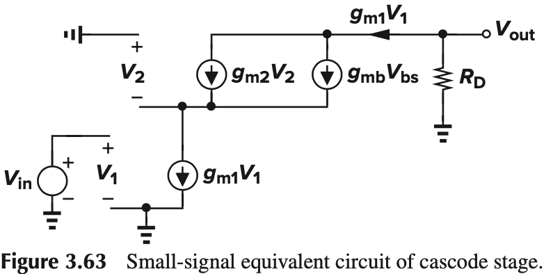
注意到输出端的电流只能是 $g_{m1}V_1$,从而 $A_v = -g_{m1}R_D$,与 $M_2$ 无关。但这是忽略了 $M_1$ 的 $r_{O1}$ 的结果($g_{mb1}$ 忽不忽略都一样),如果考虑上沟道长度调制,结果会不同。如图 Fig. 3.64,$r_O$ 会起到一个分流的作用。因此:
\[I_{D2} = g_{m1}V_\tx{in} \frac{g_{m2}+g_{mb2}}{\frac{1}{r_{O1}}+(g_{m2}+g_{mb2})}\]$(g_{m2}+g_{mb2})$ 为从 $M_2$ 源端看进去的电导。从而增益为:
\[A_v = g_{m1} \frac{g_{m2}+g_{mb2}}{\frac{1}{r_{O1}}+(g_{m2}+g_{mb2})} R_D\]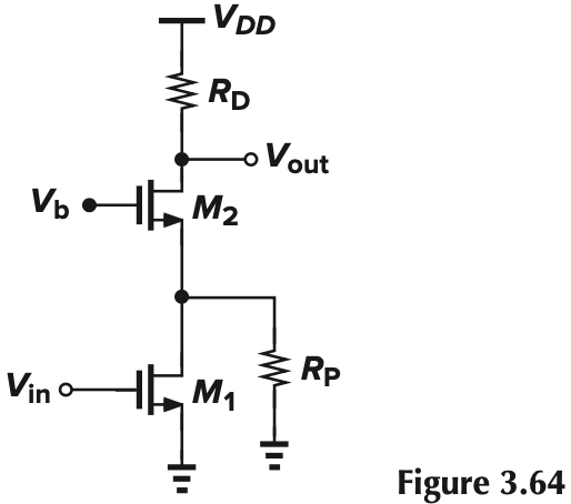

下面来计算输出电阻。注意到 $M_1$ 可以当作是 degeneration resister $r_{O1}$,从而输出电阻与前面(CS Stage with Source Degeneration)的一样:
\[\begin{aligned} R_\tx{out} &= [1+(g_{m2}+g_{mb2})r_{O2}]r_{O1}+r_{O2}\\ &\approx (g_{m2}+g_{mb2})r_{O2}r_{O1} \end{aligned}\]注意到输出电阻可以看作是 $r_{O1}$ 增大了 $(g_{m2}+g_{mb2})r_{O2}$ 倍,如果级联多级,我们可以得到很高的输出电阻(当然,trade off 是电压摆幅减小)
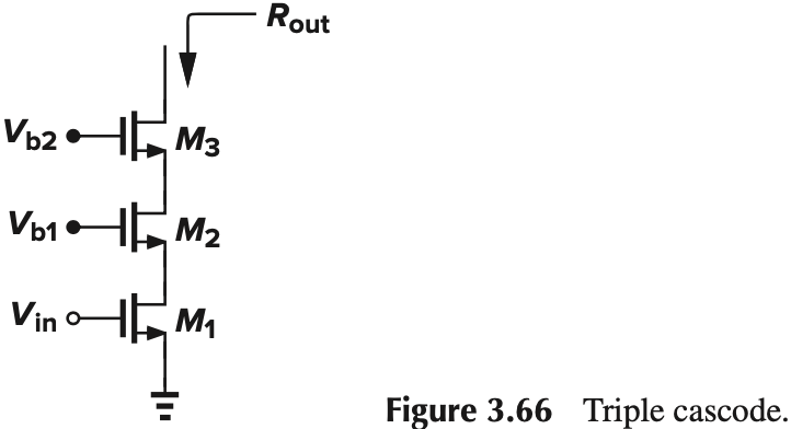
输出阻抗大有什么用呢?这里我们要介绍 Shielding Property,由于输出阻抗大,当输出电压变化时,反应到源端的电压变化就会小。我们用下面这里例子来说明。
$V_X$ is higher than $V_Y$ by $\Delta V$. Calculate the resulting difference between $I_{D1}$ and $I_{D2}$ if $λ≠0$.
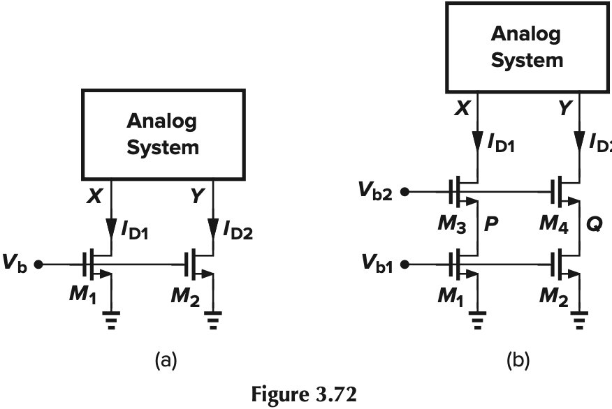
(a) We have
$$
\begin{aligned}
I_{D1}-I_{D2} &= \frac{1}{2} \mu_n C_\tx{ox} \frac{W}{L} (V_b-V_\tx{TH})^2 (\lambda V_{DS1}-\lambda V_{DS2})\\
&=\frac{1}{2} \mu_n C_\tx{ox} \frac{W}{L} (V_b - V_\tx{TH})^2 (\lambda \Delta V)
\end{aligned}
$$
(b) Cascode 起到分压的作用
$$
\begin{aligned}
\Delta V_{PQ} &= \Delta V \frac{r_{O1}}{[1+(g_{m3}+g_{mb3})r_{O3}]r_{O1}+r_{O3}}\\
&\approx \frac{\Delta V}{(g_{m3}+g_{mb3})r_{O3}}
\end{aligned}
$$
Thus,
$$
I_{D1}-I_{D2}=\frac{1}{2} \mu_n C_\tx{ox} \frac{W}{L} (V_b - V_\tx{TH})^2 \frac{\lambda \Delta V}{(g_{m3}+g_{mb3})r_{O3}}
$$
In other words, cascoding reduces the mismatch between $I_{D1}$ and $I_{D2}$ by a factor of $(g_{m3} + g_{mb3})r_{O3}$.(个人觉得这就是简单的加大电阻来减小电流变化🧐)
The shielding property of cascodes diminishes if the cascode device enters the triode region. because
$$
I_{D2}=\frac{1}{2}\mu_n C_\tx{ox} \left(\frac{W}{L}\right)_2\left[ 2(V_{b2}-V_P-V_\tx{TH2})(V_X-V_P)-(V_X-V_P)^2 \right]
$$
As $V_X$ decreases, $V_P$ also drops, so that $I_{D2}$ remains constant.
由于这个特性十分重要,我上网搜了些资料,然后在知乎上发现了一篇很好的文章 模拟电路基础之运放的增益计算(三)cascode,里面提到一种很有趣的理解方法,在此记录一下。
我们考虑共栅管的小信号模型。由于 G 是接恒压源,可看作地,从而 $V_{GS}=-V_S$,所以图中电流源方向是反的。
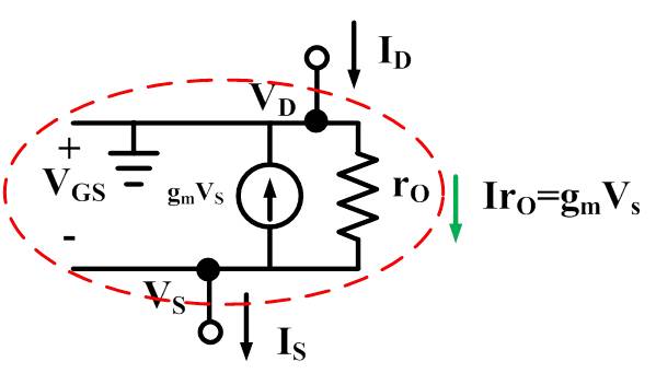
根据 KCL,如果我们把整个管看作一个结点,则 $I_S=I_D$(此处指直流大信号)。所以,这个 $g_mV_S$ 的电流,其实是“自生自灭”的!无路可退的这个 mos 人,只好把一肚子的怨气深埋在心底,自己消化掉。
所以,流过 $r_O$ 的电流,就是反方向的 $g_mV_s$,这样看来,这个 mos 上的压降 $V_{DS}$就等于 $r_og_mV_S$
因此,当我们计算 $V_D$ 的电压时,有:
\[\begin{aligned} V_D&=V_S+V_{DS}\\ &=V_S+r_Og_mV_S\\ &=(1+r_Og_m)V_S \end{aligned}\]因为我们的 $g_mr_O$ 一般能够达到一百以上,所以 $V_D$ 就大约等于 $g_mr_OV_S$。因此我们可以得到一个 Golden Rule:从 s 看到 d,电压被放大了 $g_mr_O$ 倍;从 d 看到 s,电压被缩小了 $g_mr_O$ 倍。(前提:g 接恒压源且 mos 工作在饱和区)
Folded Cascode
之前两个都是 NMOS,现在是一个 PMOS 给 NMOS 提供电流。
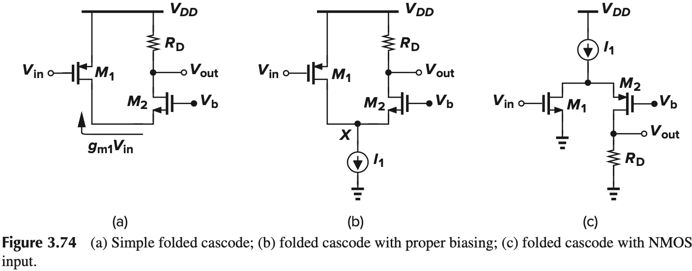
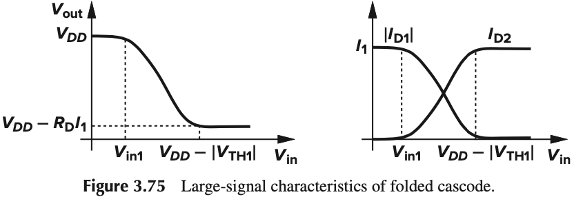
$I_1$ 用于提供直流偏置,显然 $\vert I_{D1}\vert+I_{D2}=I_1$,如果 $I_{D1}$ 变小,就会使得 $I_{D2}$ 变大,从而改变 $V_\tx{out}$
大信号分析如下:
- $V_\tx{in}>V_{DD}-\vert V_\tx{TH1} \vert$,$M_1$ is off and $M_2$ carries all of $I_1$. yielding $V_\tx{out}=V_{DD}-I_1R_D$
- $V_\tx{in}<V_{DD}-\vert V_\tx{TH1} \vert$, $M_1$ turns on in saturation, giving
- $I_{D2}$ decrease further as $V_\tx{in}$ drops. If $I_{D2}=0$, $V_\tx{out}=V_{DD}$. The $V_\tx{in}$ at this point is denoted as $V_\tx{in1}$
Thus,
\[V_\tx{in1} = V_{DD}-\sqrt{\frac{2I_1}{\mu_p C_\tx{ox}(W/L)1}} - \vert V_\tx{TH1} \vert\]