关于模型的选择(是否要考虑 $r_O,g_{mb}$):
- 在计算偏置时,不需要考虑二级效应(即 $r_O,g_{mb}$)
- 题目没有说,则默认要考虑二级效应,但如果题目太复杂,可以只考虑某些地方的二级效应,比如:
- 如果器件的漏极连接一个高阻抗(如另一个器件的源极),那么要考虑 $r_O$
关于公式的记忆:
- 只需要记考虑 $r_O,g_{mb}$ 的公式,其余公式可推出来
- 那个,共栅和其他几个公式不太一样,有人有好方法记吗?😫
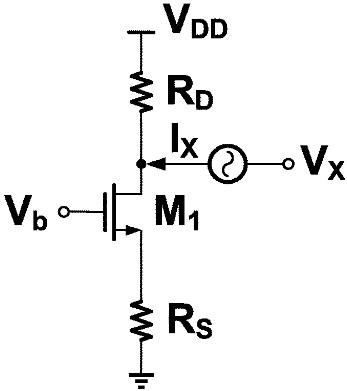
求源极负反馈的输出阻抗:

根据小信号模型,我们有:
$$
V_X = (I_X-g_mV_1-g_{mb}V_{bs})r_O+I_XR_S\\
\tx{where } V_1=V_{bs}=-I_XR_S\\
\Rightarrow V_X=[I_X+(g_m+g_{mb})R_SI_X]r_O+I_XR_S
$$
可以算出:
$$
\begin{aligned}
R_\tx{out} &= \frac{V_X}{I_X}\\
&= [1+(g_m+g_{mb})R_S]r_O+R_S\\
&= [1+(g_m+g_{mb})r_O]R_S+r_O\\
&= R_S+r_O+(g_m+g_{mb})r_OR_S
\end{aligned}
$$
求下图的输出阻抗:

只需要将上面源极负反馈的输出阻抗并联上 $R_D$ 即可:$R_\tx{out}=\{[1+(g_m+g_{mb})R_S]r_O+R_S\} \Vert R_D$
3.2 In the circuit of Fig. 3.18, assume that $(W/L)_1=50/0.5$, $(W/L)_2=50/2$, and $I_{D1}=I_{D2}=0.5 \tx{mA}$ when both devices are in saturation. Recall that $λ∝1/L$.
(a) Calculate the small-signal voltage gain.
(b) Calculate the maximum output voltage swing while both devices are saturated.

Solution:
(a) $A_v = -g_{m1}(r_{O1}\Vert r_{O2})$ where $g_m=\sqrt{2 \mu_n C_\tx{ox} \frac{W}{L} I_D}$ and $r_{O}\approx \dfrac{1}{\lambda I_D}$, therefore
$$
\begin{aligned}
g_{m1}&=\sqrt{2\times 1.34225\times 10^{-4} \times \frac{3.9}{9\times 10^{-9}}\times 50/0.5 \times 0.5 \times10^{-3}}\\
&=3.664\times 10^{-3}\\
r_{O1}&=\frac{1}{0.1\times 0.5 \times 10^{-3}}=20 {\rm k\Omega}\\
r_{O2}&=\frac{1}{0.2\times 0.5 \times 10^{-3}}=10 {\rm k\Omega}\\
A_v &= 3.664 \times 10^{-3} \times \frac{20 \times 10^3\times 10\times 10^3}{20 \times 10^3+ 10\times 10^3}\\
&=24.43
\end{aligned}
$$
(b) $M_1,M_2$ are in saturation, therefore
$$
V_\tx{in}-V_\tx{out}\leq V_\tx{TH1}\\
V_\tx{b}-V_\tx{out}\geq V_\tx{TH2}\\
\Rightarrow V_\tx{in}-V_\tx{TH1}\leq V_\tx{out}\leq V_\tx{b}-V_\tx{TH2}
$$
Assuming that $M_1$ is on the edge of the triode region, we have
$$
\begin{aligned}
I_D &= \frac{1}{2} \mu_n C_\tx{ox} (\frac{W}{L})_1(V_\tx{in}-V_\tx{TH1})^2(1+\lambda_n V_\tx{out})\\
&\leq \frac{1}{2} \mu_n C_\tx{ox} (\frac{W}{L})_1 V_\tx{out}^2(1+\lambda_n V_\tx{out})
\end{aligned}\\
$$
Solve
$$
0.5\times 10^{-3}=\frac{1}{2}\times 1.34225 \times 10^{-4}\times 50/0.5\times V_\tx{out}^2(1+0.1 V_\tx{out})\\
$$
and we have
$$
V_\tx{out,min}=0.2693 \tx{ V}
$$
Assuming that $M_2$ is on the edge of the triode region, we have
$$
\begin{aligned}
I_D &= \frac{1}{2} \mu_p C_\tx{ox} (\frac{W}{L})_1(V_{SG2}-\vert V_\tx{TH2} \vert)^2(1+\lambda_n V_{SD2})\\
&\leq\frac{1}{2} \mu_p C_\tx{ox} (\frac{W}{L})_1 V_{SD2}^2(1+\lambda_n V_{SD2})
\end{aligned}
$$
Solve
$$
0.5\times 10^{-3}=\frac{1}{2}\times 1.3835 \times 10^{-4}\times 50/2\times V_\tx{out}^2(1+0.2 V_\tx{out})\\
$$
and we have
$$
V_\tx{SD,min}=0.9967 \tx{ V}\\
V_\tx{out,max}=V_{DD}-V_\tx{SD,min}=2.003 \tx{ V}
$$
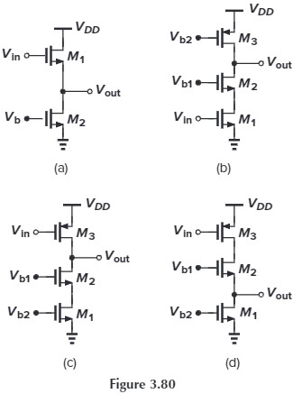
3.17 Sketch $V_\tx{out}$ versus $V
_\tx{in}$ for the circuits of Fig. 3.80 as $V_\tx{in}$ varies from 0 to $V_\tx{DD}$. Identify important transition points.

(a)
.PNG)
(b)
.PNG)
(c)
.PNG)
(d)(第二条式子多了个平方)
.PNG)
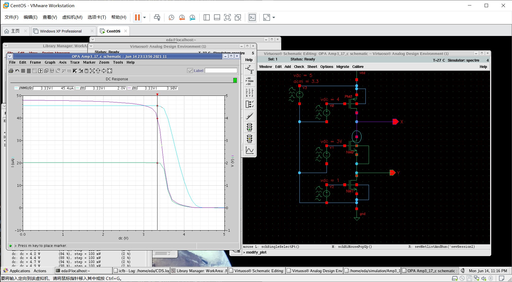
我利用 Cadence 对 (c)(d) 电路进行了仿真,仿真结果如下(注意粉色的曲线是电流⚡)

不妨先考虑三个管子均饱和的情况。此时,若减小 $V_\tx{in}$,根据 $I_{D3}=\frac{1}{2}K_p(W/L) (V_{GS3}-V_\tx{TH3})^2$,$I_D$ 会变大,此时考虑 $M_1$,由于 $V_{GS1}$ 是固定的,所以如果不考虑沟道长度调制效应,$I_{D1}$ 不会变,这就产生了矛盾。故根据 $I_{D1}=\frac{1}{2}K_n(W/L) (V_{GS1}-V_\tx{TH1})^2(1+\lambda V_{DS1})$,$V_{DS1}$ 应该变大,即 $V_Y$ 应该变大,并且 $V_Y$ 与 $V_\tx{in}$ 之间应该为 2 次关系(开口向上)。$M_2$ 的情况与 $M_1$ 类似,但由于 $V_Y$ 上升导致 $V_{GS2}$ 变小,所以要使 $I_{D2}$ 同等变大,那么 $V_{DS2}$ 增大的幅度也应该更大(对应图中两线分离的部分)。
然后考虑左边的情况,随着 $V_\tx{in}$ 减小且 $V_X$ 增大,$M_3$ 会进入 Triode,这么一来,$I_{D3}=K_p (W/L)[(V_{GS3}-V_\tx{TH})V_{DS3}-\frac{1}{2}V_{DS3}^2]$,注意到 $V_{GS3}$ 变大的同时 $V_X$ 会变大($V_{DS3}$ 变小),这两者的作用会相互抵消,导致 $I_{D3}$ 几乎不变,从而 $V_{DS2},V_{DS1}$ 也几乎不变(对应图中下面的曲线平的那一段)
(关于上一段的进一步解释。首先,既然 $I_D$ 不变,那么 $M_1,M_2$ 三端的电压也应该不变,否则电流就会变,但我们注意到图像中 $V_X$ 却会变大,这显然是矛盾的,唯一的解释就是此时不需要管 $M_2$ 的沟道长度调制效应了。另一个矛盾点是,我们易知:$\dfrac{\p I_{D3}}{\p V_{GS3}}=V_{DS}$,但图像中 $I_{D3}$ 并不随 $V_{GS3}$ 变化,所以这应该是 0,但显然 $V_{DS}\neq 0$😱,这点我实在解释不了……)
如何分析?
- 先分析输入管的初始状态(要么是 Triode 要么是 Off),并分析此时有无 $I_D$
- 然后根据 $I_D$ 相同,来得到其他管的状态
- 然后改变输入
- 由于各管的状态不会突变(Off到Sat到Tri,或反过来),故可以给
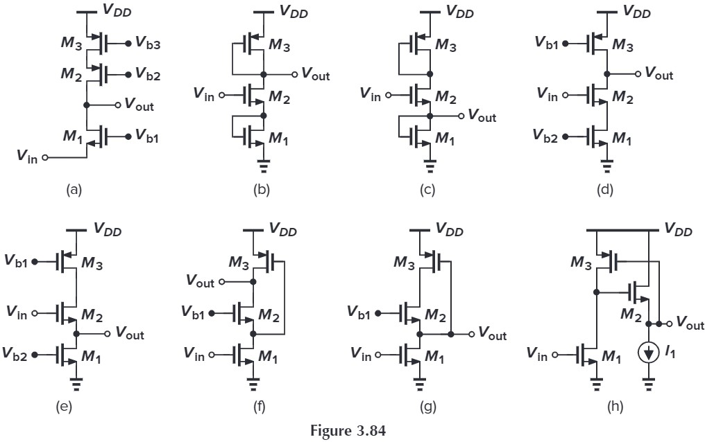
3.21 Assuming all MOSFETs are in saturation, calculate the small-signal voltage gain of each circuit in Fig. 3.84($λ \neq 0,γ=0$).

因为题目说 $\lambda=0,\gamma=0$,也就是忽略所有的体效应和沟道长度调制效应,所以 $g_{mb}=0,r_O=\infty$,所以有些题目是无解的。答案上没有忽略 $r_{O}$,那我就当 $\gamma\neq 0$ 来做。
(a)
%20solution.PNG)
(b)
.PNG)
(c)
.PNG)
(d) $M_1,M_3$ 可看作 $r_{O1},r_{O3}$,根据前面的公式:
$$
\begin{aligned}
A_v &=-G_m(R_\tx{out}\Vert R_D)\\
&= - \frac{g_mr_O}{R_S+r_O+g_mR_Sr_O}\cdot \frac{1}{\frac{1}{R_D}+\frac{1}{[R_S+r_O+g_mR_Sr_O]}}
\end{aligned}
$$
令 $R_S=r_{O1}$,$r_O=r_{O2}$,$R_D=r_{O3}$ 可得:
$$
\begin{aligned}
A_v&=-\frac{g_{m2}r_{O2}}{r_{O1}+r_{O2}+g_{m2}r_{O2}r_{O1}}\cdot \frac{1}{\frac{1}{r_{O3}}+\frac{1}{[r_{O1}+r_{O2}+g_{m2}r_{O2}r_{O1}]}}\\
&=\frac{g_{m2}r_{O2}r_{O3}}{r_{O1}+r_{O2}+r_{O3}+g_{m2}r_{O2}r_{O1}}
\end{aligned}
$$
(e)
$$
\begin{aligned}
R_\tx{out} &= \frac{r_{O3}+r_{O2}}{1+g_m r_{O2}}\\
A_v &= \frac{V_\tx{out}}{V_\tx{in}}=\frac{r_{O1}}{r_{O1}+\frac{r_{O3}+r_{O2}}{1+g_{m2}r_{O2}}}
\end{aligned}
$$
(f)
.PNG)
(g)
.jpeg)
(h)
在输入支路上,有:
$$
-(\frac{V_X}{r_{O3}}+g_{m3}V_\tx{out})=g_{m1}V_\tx{in}+\frac{V_X}{r_{O1}}
$$
在输出支路上,有:
$$
-\frac{V_\tx{out}}{r_{O2}}+g_{m2}(V_X-V_\tx{out})=0\\
\Rightarrow V_X=\frac{\frac{1}{r_{O2}}+g_{m2}}{g_{m2}}V_\tx{out}
$$
将 $V_X$ 代入输入支路表达式,有:
$$
-(\frac{1}{r_{O3}}\frac{\frac{1}{r_{O2}}+g_{m2}}{g_{m2}}V_\tx{out}+g_{m3}V_\tx{out})=g_{m1}V_\tx{in}+\frac{1}{r_{O1}}\frac{\frac{1}{r_{O2}}+g_{m2}}{g_{m2}}V_\tx{out}\\
$$
解得:
$$
A_v = \frac{V_\tx{out}}{V_\tx{in}}=-\frac{g_{m1}}{g_{m3}+(\frac{1}{r_{O3}}+\frac{1}{r_{O1}})\frac{\frac{1}{r_{O2}}+g_{m2}}{g_{m2}}}
$$