Common-Source Stage
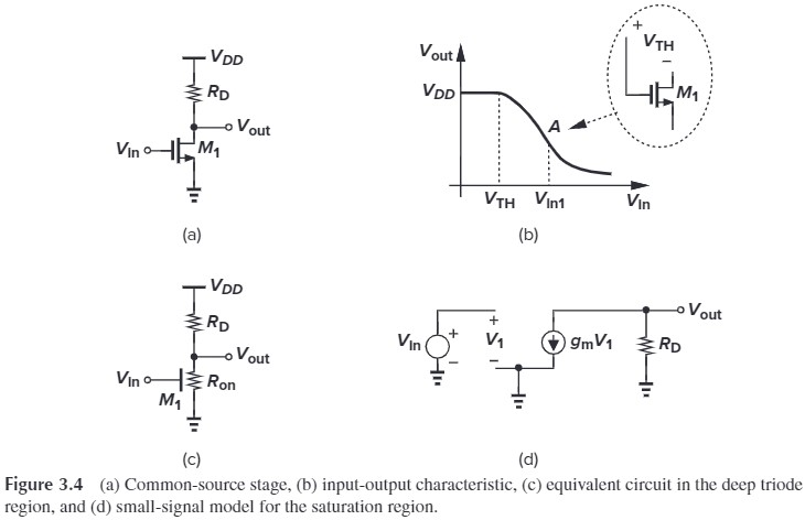
Comom-Source Stage with Resistive Load
- $V_\tx{in}=0$, $M_1$ is off, $V_\tx{out}=V_{DD}$
- $V_\tx{in}>V_\tx{TH}$, $M_1$ is in saturation, $V_\tx{out}=V_{DD}-R_D\frac{1}{2} \mu_n C_\tx{ox}\frac{W}{L}(V_\tx{in}-V_\tx{TH})^2 $
- $V_\tx{in}>V_\tx{out}+V_\tx{TH}$, $M_1$ is in the triode region, $V_\tx{out}=V_{DD}-R_D \frac{1}{2}\mu_n C_\tx{ox} \frac{W}{L}[2(V_\tx{in}-V_\tx{TH})V_\tx{out}-V_\tx{out}^2]$
We usually ensure that the MOS is in saturation. The small-signal gain is
\[\begin{aligned} A_v &= \frac{\p V_\tx{out}}{\p V_\tx{in}}\\ &=-R_D \mu_n C_\tx{ox} \frac{W}{L}(V_\tx{in}-V_\tx{TH})\\ &=-g_m R_D \end{aligned}\]The small-signal model of Fig 3.4(d) yiels the same result.
And we can rewrite $g_m$ and $R_D$ as
\[g_m=\sqrt{2\mu_n C_\tx{ox}\frac{W}{L}I_D}\\ R_D = \frac{V_{RD}}{I_D}\]therefore
\[\begin{aligned} A_v &= -\sqrt{2\mu_n C_\tx{ox}\frac{W}{L}I_D} \frac{V_{RD}}{I_D}\\ &= -\sqrt{2\mu_n C_\tx{ox}\frac{W}{L}} \frac{V_{RD}}{\sqrt{I_D}} \end{aligned}\]How to maxiumize $A_v$?
- increasing $W/L$
- leads to grater device capacitances
- increasing $V_{RD}$
- limits the maximum voltage swings
- The maximum output is $V_{DD}$, the mimimum output is $V_\tx{in}-V_\tx{TH}$, ideal $V_{RD}$ should be in the middle of max and min output voltage.
- decreasing $I_D$
- $R_D$ must increase to abtain the same DC output, leading to a greater time constant at the output node
it seems that 3. is more acceptable.
For large values of $R_D$, the effect of channel-length modulation in $M_1$ becomes significant.
\[\begin{aligned} A_v &= \frac{\p V_\tx{out}}{\p V_\tx{in}}\\ &= \frac{\p}{\p V_\tx{in}} \left\{ V_{DD}- R_D\frac{1}{2} \mu_n C_\tx{ox}\frac{W}{L}(V_\tx{in}-V_\tx{TH})^2 (1+\lambda V_\tx{out}) \right\}\\ &= - R_D\mu_n C_\tx{ox}\frac{W}{L}(V_\tx{in}-V_\tx{TH}) (1+\lambda V_\tx{out})\\ &\quad -R_D\frac{1}{2} \mu_n C_\tx{ox}\frac{W}{L}(V_\tx{in}-V_\tx{TH})^2 (\lambda \frac{\p V_\tx{out}}{\p V_\tx{in}})\\ &= -R_D g_m - \frac{R_D}{r_O} A_v\\ \therefore A_v &= -g_m \frac{r_O R_D}{r_O+R_D}\\ \frac{1}{r_O}&= \frac{1}{2} \mu_n C_\tx{ox}\frac{W}{L}(V_\tx{in}-V_\tx{TH})^2 \lambda \end{aligned}\\\]
We can use the small-signal model to get the same result:
\[g_m V_1 + V_\tx{out} \cdot (\frac{1}{r_O}+\frac{1}{R_D})=0\\ 代入 V_1 = V_\tx{in} 有\\ g_m V_\tx{in} + V_\tx{out} \cdot (\frac{1}{r_O}+\frac{1}{R_D})=0\\ \Rightarrow A_v = \frac{V_\tx{out}}{V_\tx{in}} = -g_m (r_O \| R_D)\]注意区分小信号的 $V_\tx{in},V_\tx{out}$ 与 大信号的 $V_\tx{in},V_\tx{out}$
Calculate the small-signal voltage gain of the circuit. (assuming $M_1$ is biased in saturation)
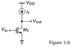
Current source has an $R_D = \infty$, therefore
$$
A_v = -g_m r_O
$$
Called the “intrinsic gain 本征增益” of a transistor, this quantity represents the maximum voltage gain that can be achieved using a single device.
The total drain current of $M_1$ is
$$
\begin{aligned}
I_{D1}&=\frac{1}{2} \mu_n C_\tx{ox}\frac{W}{L}(V_\tx{in}-V_\tx{TH})^2 (1+\lambda V_\tx{out})\\
&=I_1
\end{aligned}
$$
注意到 $I_1$ 保持不变,而 $V_\tx{in}$ 如果增加,则 $V_\tx{out}$ 必须减小。但这两者并不是严格的线性关系。
CS Stage with Diode-Connected Load
it’s hard to fabricate resistors with the values wanted. Therefore we replace $R_D$ with a diode-connected MOS transistor (Fig.3.10)

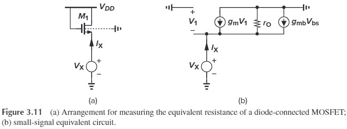
With body effect and channel-length modulation (Fig. 3.11), we have
\[g_m V_1 + g_{mb} V_{bs} +I_X-\frac{V_X}{r_O}=0\\ 代入 V_1=-V_X, V_{bs}=-V_X有\\ (g_m+g_{mb})V_X+\frac{V_X}{r_O}=I_X\\ \Rightarrow \frac{V_X}{I_X} = \frac{1}{g_m+g_{mb}+1/r_O} \approx \frac{1}{g_m+g_{mb}} \tag{3.21}\](此处是为了说明 diode-connected MOS 的工作特性就像电阻一样,电阻值是 $1/g_m$、$1/g_{mb}$、$r_O$ 的并联。注意此时 MOS 一定在饱和区)
计算下图电路中从源端看进去的电阻($\lambda=0$,即忽略沟道长度调制效应)
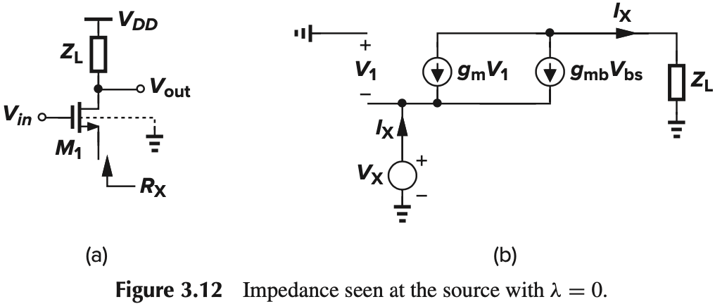
对比 Fig. 3.12(b) 与 Fig. 3.11(b),这两个电路几乎一样,计算方法也是相同的:
$$
\because V_1=-V_X, V_{bs}=-V_X\\
g_m V_X+g_{mb}V_X=I_X\\
\therefore \frac{V_X}{I_X} = \frac{1}{g_m + g_{mb}} \tag{3.26}
$$
可以看出最后结果和上面忽略了 $r_O$ 的结果是一样的。所以我们认为,只要不考虑 $r_O$,无论 MOS 管怎么连接,源端看进去的电阻都是 $\dfrac{1}{g_m} \Vert \dfrac{1}{g_{mb}}$。(相当于屏蔽了漏端电阻)
那么如果我们考虑 $r_O$ 会怎样呢?我们可以列出如下式子:
$$
V_X = I_X Z_L + (I_X - g_m V_X - g_{mb} V_X ) r_O\\
\therefore \frac{V_X}{I_X} = \frac{Z_L+r_O}{1+(g_m+g_{mb})r_O}
$$
剧透一下,分母叫做 degenerated factor,这章后面会详细讲。
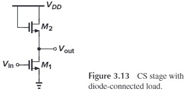
With negligible channel-length modulation, common-source stage with a diode-connected load has
\[\begin{aligned} A_v &= -g_{m1} R_D\\ &= - g_{m1}\frac{1}{g_{m2}+g_{mb2}}\\ &= -\frac{g_{m1}}{g_{m2}} \frac{1}{1+\eta} \end{aligned}\\ \tx{where } \eta = g_{mb2}/g_{m2}\]Since $g_{m} = \sqrt{\frac{1}{2}\mu_n C_\tx{ox}(W/L)I_D}$,
\[\begin{aligned} A_v &= - \sqrt{\frac{2\mu_n C_\tx{ox}(W/L)_1I_{D1}}{2\mu_n C_\tx{ox}(W/L)_2I_{D2}}} \frac{1}{1+\eta}\\ &= - \sqrt{\frac{(W/L)_1}{(W/L)_2}} \frac{1}{1+\eta} \end{aligned}\]This equation reveals an interesting property: if the variation of $\eta$ with the output voltage is neglected, the gain is independent of the bias currents and voltages (so long as $M_1$ stays in saturation). In otherwords, as the input and output signal levels vary, the gain remains relatively constant, indicating that the input-output characteristic is relatively linear.
(从大信号的角度说明上述内容)$M_2,M_1$ share the same $I_D$, therefore
\[\begin{aligned} I_{D1}&=I_{D2}\\ \frac{1}{2} \mu_n C_\tx{ox} \left(\frac{W}{L}\right)_1 (V_\tx{in}-V_\tx{TH})^2 &= \frac{1}{2} \mu_n C_\tx{ox} \left(\frac{W}{L}\right)_2 (V_{DD}-V_\tx{out}-V_\tx{TH})^2\\ \sqrt{\left(\frac{W}{L}\right)_1} (V_\tx{in}-V_\tx{TH1}) &=\sqrt{\left(\frac{W}{L}\right)_2} (V_{DD}-V_\tx{out}-V_\tx{TH2}) \end{aligned}\]可以看出 $V_\tx{out}$ 与 $V_\tx{in}$ 是线性关系。
The small-signal gain can also be computed by differentiating both sides with respect to $V_\tx{in}$
\[\sqrt{\left(\frac{W}{L}\right)_1} =\sqrt{\left(\frac{W}{L}\right)_2} (-\frac{\p V_\tx{out}}{\p V_\tx{in}}-\frac{\p V_\tx{TH2}}{\p V_\tx{in}})\]where
\[\frac{\p V_\tx{TH2}}{\p V_\tx{in}} = \frac{\p V_\tx{TH2}}{\p V_\tx{out}} \frac{\p V_\tx{out}}{V_\tx{in}}\]recall that
\[g_{mb}=g_m \left(-\frac{\p V_\tx{TH}}{\p V_{BS}}\right)\\ 代入 V_\tx{TH2}=V_\tx{TH},V_{BS}=-V_\tx{out}\\ \Rightarrow \frac{\p V_\tx{TH2}}{\p V_\tx{out}} = \frac{g_{mb}}{g_m}=\eta\]therefore
\[\frac{\p V_\tx{out}}{\p V_\tx{in}}=-\sqrt{\frac{(W/L)_1}{(W/L)_2}} \frac{1}{1+\eta}\]我们继续讨论一下 $V_\tx{in}$ 从 0 变大时,对应的 $V_\tx{out}$
- $V_\tx{in}<V_\tx{TH1}$,这样的话,$I_{D1}$ 为 0,$V_\tx{out}$ 应该为 $V_{DD}$,但实际中会有寄生电容,会减缓 $V_\tx{out}$ 趋向 $V_{DD}$,所以我们一般认为 $V_\tx{out}=V_{DD}-V_\tx{TH2}$ (此时 $M_2$ 有点像三极管,$V_{DD}$ 经过 gs 压降后到 $V_\tx{out}$)
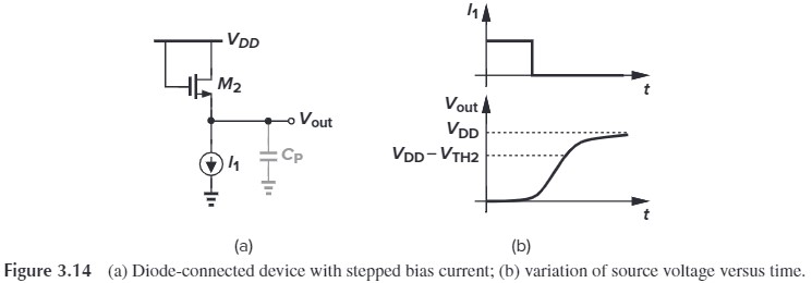
- $V_\tx{in}>V_\tx{TH1}$,就是上面讨论的情况
- $V_\tx{in}-V_\tx{TH1}>V_\tx{out}$,此时 $M_1$ 进入可变电阻区,输入输出非线性
总结为下图:

说说这种用法的坏处:注意到要增大增益,$\sqrt{\frac{(W/L)_1}{(W/L)_2}}$ 要尽可能大,也就是说 $(W/L)_1$ 要大而 $(W/L)_2$ 要小。如果增益为 $10$,忽略 $\eta$,那么 $M_1$ 的尺寸要是 $M_2$ 的 100 倍!!这样的话版图比例不平衡。这体现了 trade-off
最后我们模仿上面的过程,来分析一下把 $M_2$ 换成 PMOS 的情况:
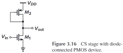
我们省略微分的过程,直接有(这里符号好像有问题):
\[A_v = -\sqrt{ \frac{\mu_n(W/L)_1}{\mu_p (W/L)_2}} \frac{1}{1+\eta}\\ = \frac{\vert V_{GS2}-V_\tx{TH2} \vert}{V_{GS1}-V_\tx{TH1}} \frac{1}{1+\eta}\]这里我们要说明另一个 trade-off:$V_\tx{out}$ 被两个东西限制,一个是 $M_1$ 的 overdrive voltage,即 $V_\tx{out}>V_\tx{in}-V_\tx{TH}$,另一个是 $M_2$ 的 threshold voltage,即 $V_\tx{out}<V_{DD}-\vert V_\tx{TH}\vert$
最后我们不加证明的给出考虑了沟道长度调制的增益:
\[A_v = -g_{m1}(r_{O1} \Vert \frac{1}{g_{m2}}\Vert r_{O2})\]其实就是将之前的 $R_D$ 换成了 $\frac{1}{g_{m2}}\Vert r_{O2}$,即 diode-connected MOS 的源端电阻。
悖论:有两种方法计算 diode-connected PMOS 的电路的增益:
$$
\vert A_v \vert = \frac{g_{m1}}{g_{m2}}
$$
方法一:由于 $g_{m} = \sqrt{\frac{1}{2}\mu_n C_\tx{ox}(W/L)I_D}$,并且 $\mu_n \left(\frac{W}{L}\right)_1(V_{GS1}-V_{TH1})^2 =\mu_p \left(\frac{W}{L}\right)_2(V_{GS2}-V_{TH2})^2$,所以有:
$$
\vert A_v \vert = \sqrt{ \frac{\mu_n(W/L)_1}{\mu_p (W/L)_2}}\\
= \frac{\vert V_{GS2}-V_\tx{TH2} \vert}{V_{GS1}-V_\tx{TH1}}
$$
方法二:由于 $g_m=\mu_n C_\tx{ox}\frac{W}{L}(V_{GS}-V_\tx{TH})$,所以有:
$$
\vert A_v \vert = \frac{\mu_n (W/L)_1(V_{GS1}-V_\tx{TH1})}{\mu_p (W/L)_2\vert V_{GS2}-V_\tx{TH2} \vert}
$$
这两种方法得出了两个截然不同的结果:一个与 $\vert V_{GS2}-V_\tx{TH2}\vert$ 成正比,一个成反比。为什么会这样?
注意到这两个结果可以通过上下乘以 $I_D = \frac{1}{2} \mu_n C_\tx{ox} \frac{W}{L}(V_{GS}-V_\tx{TH})^2$ 来互换,因此这两个结果是等价的。但为什么一个是正比而一个是反比呢?
原因是:这两个既不成正比,也不成反比,而是 $A_v$ 与 $\vert V_{GS2}-V_\tx{TH2}\vert$ 无关。因为当 $\vert V_{GS2}-V_\tx{TH2}\vert$ 增大时,根据 $I_{D1}=I_{D2}$,$(V_{GS1}-V_\tx{TH1})$ 也要同等增大,使得 $A_v$ 保持不变。
CS Stage with Current-Source Load
According the relationship $A_v = -g_m R_D$, we need to increase the load impedance of the CS stage. However, increasing the load resistance translates to a large dc drop across the load, thereby limiting theoutput voltage swing.
A solution to that is to replace the load with a current source, which we have discussed before.

The gain is given by is
\[A_v = -g_{m1} (r_{O1}\|r_{O2})\](补充:为什么 M2 的小信号模型是$r_{O2}$ 而不是像 diode-connected 那样?因为 $r_O$ 的定义就是 $\dfrac{\p V_{DS}}{\p I_D}$,并且 $V_{GS2}=V_b-V_{DD}$、$V_{SB2}=V_{DD}$ 是恒定的,可看作 AC ground,所以不存在 $g_m,g_{mb}$)
这样的好处是,MOS 不需要像电阻那样遵守欧姆定律,它上面的电压降最小能达到 $|V_{DS2,\min}|=|V_{GS2}-V_\tx{TH2}|$。
虽然 current-source loads 相比于 resistive load 增大了增益,但也限制了输出摆幅。

下面我们来讨论一下器件尺寸 $L$ 对 $A_v$ 的影响。我们回顾一下 $r_{O}$ 的定义式:
\[r_O=\frac{1}{\lambda I_D}\]而 $\lambda \propto \dfrac{1}{L}$,所以如果我们增大 $L_1$,根据
\[g_{m1}r_{O1}=\sqrt{2 \left(\dfrac{W}{L}\right)_1 \mu_n C_\tx{ox} I_D} \dfrac{1}{\lambda I_D}\\ 且 \lambda \propto \frac{1}{L_1}\]$g_m \propto \sqrt{L_1}$,所以 $L_1 \uparrow \Rightarrow A_v \uparrow$
同理,可以通过增加 $L_2$ 来增大 $r_{O2}$,从而提高增益。但这种情况下,需要更大的 $\vert V_{DS2}\vert$ 来保证 $M_2$ 工作在饱和区。
为什么 $L_2$ 增大,需要更大的 $\vert V_{DS2}\vert$?
解释:在 $I_D$ 不变的情况下,我们有:
$$
V_{GS}-V_\tx{TH} \propto 1/\sqrt{(W/L)}
$$
而要保证 $M_2$ 工作在饱和区,必须有:
$$
V_{DS}>V_{GS}-V_\tx{TH}
$$
从而 $L_2$ 增大会导致(相同电流下) $V_{DS}$ 增大。
CS Stage with Active Load
current-source load 中,PMOS serves as a constant current source,如果我们把 PMOS 也当作 amplifier 用,就叫做 Active Load,这种接法也叫 complementary CS stage

其实这就是 CMOS inverter。因为有两个放大器,所以增益会变大,我们可以用小信号模型求出
\[-(g_{m1}+g_{m2})V_\tx{in} \cdot (r_{O1}\Vert r_{O2}) = V_\tx{out}\\ \Rightarrow A_v = -(g_{m1}+g_{m2})(r_{O1}\Vert r_{O2})\]其实这个也可以用叠加法来求(将两个 current-source load 叠加)
CS Stage with Triode Load
A MOS device operating in the deep triode region behaves as a resistor andcan therefore serve as the load in a CS stage. The resistor value can be calculated as
\[R_\tx{on2} = \frac{1}{\mu_p C_\tx{ox}(W/L)_2 (V_{DD}-V_b-\vert V_\tx{THP} \vert )}\]
- 缺点:$R_\tx{on2}$ 会随工艺和温度变化
- 优点:消耗的电压裕度小于 Diode-connect($V_\tx{out,max}=V_{DD}$)
CS Stage with Source Degeneration
$I_D$ 与 overdrive voltage $(V_{DS}-V_\tx{TH})$ 之间是非线性关系,这就导致输出是非线性的。之前我们说过可以用 diode-connected load 来修正非线性效应,这里我们介绍另一种方法:增加 $R_S$
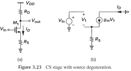
作用过程:$V_\tx{in} \uparrow$ $\Rightarrow$ $I_D \uparrow$ $\Rightarrow$ $V_{R_S} \uparrow$ $\Rightarrow$ $V_{GS} \downarrow$ $\Rightarrow$ $I_D \downarrow$
下面来计算一下 $A_v$:
\[\begin{aligned} A_v &= \frac{\p V_\tx{out}}{\p V_\tx{in}}\\ &=\frac{\p (V_{DD}-I_DR_D)}{\p V_\tx{in}}\\ &=-\frac{\p I_D}{\p V_\tx{in}}R_D\\ &=-G_m R_D \end{aligned}\]其中,
\[\begin{aligned} G_m &= \frac{\p I_D}{\p V_\tx{in}}\\ &= \frac{\p I_D}{\p V_{GS}} \frac{\p V_{GS}}{\p V_\tx{in}}\\ \frac{\p V_{GS}}{\p V_\tx{in}}&=\frac{\p }{\p V_\tx{in}}(V_\tx{in}-I_DR_S)\\ &=1-R_S \frac{\p I_D}{\p V_\tx{in}}\\ &=1-R_S G_m\\ \frac{\p I_D}{\p V_{GS}}&=g_m \end{aligned}\]算得:
\[G_m = (1-R_SG_m)g_m\\ \Rightarrow G_m = \frac{g_m}{1+g_mR_S}\]最终:
\[\begin{aligned} A_v &= -G_m R_D\\ &=\frac{-g_mR_D}{1+g_mR_S}\\ &=\frac{-R_D}{1/g_m+R_S} \end{aligned}\]$G_m$ or $A_v$ is degenerated by a factor of $1+g_mR_S$. 我们可以这样记忆 $A_v$,分子 $R_D$ 是从 $V_{DD}$ 往下看的电阻,而分母 $1/g_m+R_S$ 则是从 GND 往上看的电阻。
下面来考虑有体效应和沟道长度调制效应的情形,为了简化分析,我们先不考虑 $R_D$

With body effect and channel-length modulation considered, we have (Fig. 3.24)
\[V_X = (\frac{V_X}{R_S}-g_mV_1-g_{mb}V_{bs}) r_O\\ \tx{where } V_1=V_\tx{in}-V_X\\ V_{bs}=V_X\\ V_X=I_\tx{out}R_S\]代入后,
\[\begin{aligned} I_\tx{out} &= g_m V_1 - g_{mb} V_X -\frac{I_\tx{out}R_S}{r_O}\\ &= g_m(V_\tx{in}-I_\tx{out}R_S)+g_{mb}(-I_\tx{out}R_S)-\frac{I_\tx{out}R_S}{r_O} \end{aligned}\\ \Rightarrow I_\tx{out} = \frac{g_mV_\tx{in}}{1+g_m R_S+g_{mb}R_S+\frac{R_S}{r_O}}\\ \begin{aligned} G_m&=\frac{I_\tx{out}}{V_\tx{in}}\\ &=\frac{g_m r_O}{R_S+r_O+(g_m+g_{mb})R_S r_O}\\ &=\frac{g_m/R_S}{1/r_O+1/R_S+g_m+g_{mb}} \end{aligned}\]Typically,$(g_m+g_{mb})r_O\gg 1$,所以我们会忽略分母中的 $R_S$ 项,从而
\[G_m \approx \frac{g_m}{1+(g_m+g_{mb})R_S}\]$G_m$ or $A_v$ is degenerated by a factor of $1+(g_m+g_{mb})R_S$(之前是 $1+g_m R_S$)
为什么说 degenerated CS stage 可以改善非线性性呢?我们可以对比 $R_S=0$ 与 $R_S\neq 0$ 的 $I_D$ 与 $G_m$:
- $R_S=0$(饱和区)
- $I_D=\frac{1}{2}\mu_n C_\tx{ox} (W/L)(V_\tx{in}-V_\tx{TH})^2$
- $g_m=\mu_n C_\tx{ox}(W/L)(V_\tx{in}-V_\tx{TH})$
- $R_S\neq0$(饱和区)
- $I_D=\frac{1}{2}\mu_n C_\tx{ox} (W/L)(V_\tx{in}-I_D\cdot R_S-V_\tx{TH})^2$
- 😀“易”算出:
- $I_D=\dfrac{1}{R_S} \left( V-\dfrac{1 \pm \sqrt{1- 4kR_SV}}{2kR_S}\right)$,其中,$k=\frac{1}{2}\mu_n C_\tx{ox}(W/L)$,$V=V_\tx{in}-V_\tx{TH}$
- $G_m=\dfrac{1}{1/g_m+(1+g_{mb}/g_m)R_S}$,$V_\tx{in}\uparrow \Rightarrow g_m \uparrow \Rightarrow G_m=1/R_S$
- $I_D=\frac{1}{2}\mu_n C_\tx{ox} (W/L)(V_\tx{in}-I_D\cdot R_S-V_\tx{TH})^2$
Fig. 3.25(a) 对应的是 Resistive load,Fig. 3.25(b) 对应的是 degenerated laod. 可以看出,在 $V_\tx{in}$ 较大时,degenerated load 的 $G_m$ 趋向于一个恒定值 $1/R_S$ 说明输入输出近似于线性的。


下面我们来考虑输出阻抗。根据小信号模型,我们有:
\[V_X = (I_X-g_mV_1-g_{mb}V_{bs})r_O+I_XR_S\\ \tx{where } V_1=V_{bs}=-I_XR_S\]可以算出:
\[\begin{aligned} R_\tx{out} &= \frac{V_X}{I_X}\\ &= [1+(g_m+g_{mb})R_S]r_O+R_S\\ &= [1+(g_m+g_{mb})r_O]R_S+r_O\\ &= R_S+r_O+(g_m+g_{mb})r_OR_S \end{aligned}\]这里后面的三个等号对应三种理解方式,我们一般采取的是第二种理解方式,即从漏端往下看,$R_S$ 增大了 $[1+(g_m+g_{mb})r_O]$ 倍,再加上 $r_O$(这种方式在后面多级 Cascode 会用到)。但从记忆的角度,第一种方式显然好记一点,因为 $r_O$ 前面的就是 Degeneration Factor
还有另一种计算 $R_\tx{out}$ 的方法是这样的:我们在从源端加一路跳变电压 $\Delta V$,求跳变电流 $\Delta I$(Fig. 3.30),我们可以等效为 Fig 3.30(c)(还记得之前我们说过从源端看进去的电阻是 $1/(g_m+g_{mb})$吗?)
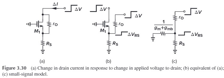
从而有:
\[\Delta I = \frac{\Delta V_{R_S}}{R_S}= \Delta V \frac{\frac{1}{g_m+g_{mb}}\Vert R_S}{\frac{1}{g_m+g_{mb}}\Vert R_S+r_O} \Big/R_S\\ =\Delta V \frac{1}{[1+(g_m+g_{mb})]R_Sr_O+R_S}\] \[R_\tx{out}=\frac{\Delta V}{\Delta I}=\frac{1}{[1+(g_m+g_{mb})R_S]r_O+R_S}\]以上都没有考虑 $R_D$,实际总的输出电阻要并联上 $R_D$
最后我们来计算考虑了 body effect 和 channel-length modulation 的增益(考虑 $R_D$)。

首先,$R_S$ 的电流与 $R_D$ 上的电流相同,都是 $-\dfrac{V_\tx{out}}{R_D}$,所以有:
\[\begin{aligned} I_{r_O} &= -\frac{V_\tx{out}}{R_D}-(g_m V_1 + g_{mb}V_{bs})\\ &= - \frac{V_\tx{out}}{R_D}-\left[g_m\left(V_\tx{in}+V_\tx{out}\frac{R_S}{R_D}\right)+g_{mb}V_\tx{out}\frac{R_S}{R_D}\right] \end{aligned}\]代入 $V_\tx{out}$ 的表达式:
\[\begin{aligned} V_\tx{out}&=I_{r_O} r_O-\frac{V_\tx{out}}{R_D}R_S\\ &=\left\{ - \frac{V_\tx{out}}{R_D}-\left[g_m\left(V_\tx{in}+V_\tx{out}\frac{R_S}{R_D}\right)+g_{mb}V_\tx{out}\frac{R_S}{R_D}\right] \right\} r_O-\frac{V_\tx{out}}{R_D}R_S\\ &=-r_O\frac{V_\tx{out}}{R_D}-g_m r_O V_\tx{in} +(g_m+g_{mb})r_OV_\tx{out}\frac{R_S}{R_D}-V_\tx{out}\frac{R_S}{R_D} \end{aligned}\]最终算得:
\[A_v = \frac{V_\tx{out}}{V_\tx{in}}=\frac{-g_mr_OR_D}{R_D+R_S+r_O+(g_m+g_{mb})R_Sr_O}\]这么复杂,我们要如何记呢?我们可以将 $A_v$ 改写成:
\[\begin{aligned} A_v &= - \frac{g_mr_O}{R_S+r_O+(g_m+g_{mb})R_Sr_O}\cdot \frac{1}{\frac{1}{R_D}+\frac{1}{R_S+r_O+(g_m+g_{mb})R_Sr_O}}\\ &=- \frac{g_mr_O}{r_O+[1+(g_m+g_{mb})r_O]R_S}\cdot \frac{1}{\frac{1}{R_D}+\frac{1}{r_O+[1+(g_m+g_{mb})r_O]R_S}}\\ &=-G_m(R_\tx{out}\Vert R_D) \end{aligned}\]后一项就是从 $V_\tx{out}$ 看进去的电阻并联。前一项就是电流分流。
Summary
| CS stage with … | Resistive Load | Diode-Connected Load | Current-Source Load | Active Load | Triode Load | Source Degeneration |
|---|---|---|---|---|---|---|
| $A_v$, $\eta=\lambda=0$ | $-g_m R_D$ | $- g_{m1}\dfrac{1}{g_{m2}+g_{mb2}}$ 或 $-\dfrac{g_{m1}}{g_{m2}} \dfrac{1}{1+\eta_2}$ 或 $-\sqrt{\frac{(W/L)_1}{(W/L)_2}} \dfrac{1}{1+\eta}$ |
$-g_{m1} (r_{O1}|r_{O2})$ | 不存在 | $R_D=R_\tx{on2}$ | $-\dfrac{1}{1/g_m+R_S}R_D$ |
| $A_v$, $\eta,\lambda\neq 0$ | $-g_m (r_O \Vert R_D)$ 体效应无影响 |
把 $R_D = \dfrac{1}{g_{m2}+g_{mb2}}$ 代入左边即可 | 把 $R_D=r_O$ 代入左边即可 | $-(g_{m1}+g_{m2})(r_{O1}\Vert r_{O2})$ | $R_D=R_\tx{on2}$ | $-G_m(R_\tx{out}\Vert R_D)(见上面)$ |
- $g_m = \mu_n C_\tx{ox} \frac{W}{L}(V_\tx{in}-V_\tx{TH})$
- $r_O=\dfrac{1}{\lambda I_D}$
- $g_{mb}=g_m \dfrac{\gamma}{2\sqrt{2\Phi_F+V_{SB}}}$
实际上我们只需要记 Source Degeneration 的公式即可,而这个公式也不难记。方法是先死记 degeneration factor $[1+(g_m+g_{mb})r_O]$,即 $R_S$ 放大的倍数;然后再记不考虑 $R_D$ 的 $R_\tx{out}=[1+(g_m+g_{mb})r_O]R_S+r_O$,以及 $G_m = \dfrac{g_mr_O}{R_\tx{out}}$,最后得到 $A_v = -G_m(R_\tx{out}\Vert R_D)$。如果要求其他,令 $R_S=0$ 即可。
除了利用 $A_v = G_m R_\tx{out}$ 外,另一种记忆方法是 $A_v = -\dfrac{R_\tx{drain}}{R_\tx{source}}$,即,举个例子:对于 Diode-Connected Stage,我们有:
\[A_v = \frac{-i_d \cdot \frac{1}{g_{m2}}}{i\cdot \frac{1}{g_{m1}}}=\frac{\frac{1}{g_{m2}}}{\frac{1}{g_{m1}}}=-\frac{g_{m1}}{g_{m2}}\]再举个例子,对于 Degeneration,我们有:
\[A_v = \frac{R_D}{1/g_m+R_S}\]甚至也可以考虑上 $r_O$:
\[A_v = \frac{R_D \Vert \{ r_O+[1+(g_m+g_{mb})r_O]R_S\}}{R_S+\frac{R_D+r_O}{1+(g_m+g_{mb})r_O}}\]