第一章 介绍
(1)什么是数字系统?What’s digital system?
- Digital system is based on digital circuits.
- A Digital System recognizes, processes and outputs only a finite or discrete number of values of some parameter.
Basic parts of digital systems: Memory, Processor, Peripheral control
(2)自顶向下的设计思想
- Top-down(自顶向下): partition is not constrained by what is available
- Increased productivity: shorter development cycle, more product features
- Reduced non-recurring engineering (NRE) costs
- Design reuse facilitated
- Flexibility in design changes
- Rapidly explore alternatives: architectures, implementation technologies reduced time-to-market
- Bottom-up(自底向上): somewhat misnomer. partition is constrained by realistic condition.
- inefficient
- has no simulation tools, error is terrible
(3)利用EDA的数字系统设计特点
不知道
第二章 语法
基本结构及数据类型
(1)Features of VHDL
a) Strong capability of system description b) Independence of device and hardware technique c) IEEE standard d) Flexible design method(behav,struc,dataflow) e) Readable program f) As an HDL,executed concurrently
(2)Structure of VHDL
LIBRARY, Package, Entity, Architecture, Configuration 其它:Block, Sub-program
一个完整的 VHDL 程序必须有:LIBRARY, Package, Entity, Architecture
(3)Default Library(默认库):STD,work
LIBRARY IEEE 中的库:
- std_logic_1164 (std_logic types & related functions)
- std_logic_arith (arithmetic functions)
- std_logic_signed (signed arithmetic functions)
- std_logic_unsigned (unsigned arithmetic functions)
用法:
library IEEE;
use IEEE.std_logic_1164.all;
(3)Entity —— outward appearence,格式:
entity <entity_name> is
  generic(常数名:数据类型:=设定值;
          ...);
  port(端口名:端口方向 数据类型;
       ...);
end <entity_name>;
端口的方向及用法:
- in 输入 can not be assign the value
- out 输出 can not be the source of assignment
- inout 双向 bi-directional port
- buffer 输出缓冲 serve as an output,its value can be reloaded
预定义的数据类型:
| 数据类型 | 说明 | 能否用于综合 |
|---|---|---|
Boolean |
取值为 true 和 false,用于关系运算 | ✅ |
Bit |
取值为 0 和 1,用于逻辑运算 | ✅ |
Bit_vector |
Bit 类型的数组,用于逻辑运算 | ✅ |
Integer |
32位有符号整数,用于数值运算 | ✅ |
Real |
-1E38~1E38 | ❌ |
Time |
包括整数和单位,之间至少留一个空格,如 20 ms,30 us |
❌ |
其中,integer 要用 range 0 to 9 指定范围。
IEEE.std_logic_1164.all 中定义的数据类型:std_logic 和 std_logic_vector。 std_logic 可以取以下值 (以下值必须大写!):
| 信号值 | 定义 |
|---|---|
| ‘U’ | 未初始化 uninitialized |
| ‘X’ | 强未知 forcing unknow |
| ‘0’ | 强0 forcing 0 |
| ‘1’ | 强1 forcing 1 |
| ‘Z’ | 高阻态 high impedance |
| ‘W’ | 若未知 weak unknown |
| ‘L’ | 弱0 weak 0 |
| ‘H’ | 弱1 weak 1 |
| ’-‘ | 不关心 don’t care |
不同信号值遇到一起的话:强大于弱,未知大于01,01相遇变未知,高阻遇啥就是啥,不关心遇啥都未知。
用户自定义的数据类型(在后面的状态机中用到):
- 枚举类型:
TYPE week IS (sun, mon, tue, wed, thu, fri, sat) - 数组类型(同类型):
TYPE byte IS ARRAY(7 downto 0) OF BIT - 记录类型(不同类型):
TYPE GlitchDataType IS RECORD
    schedtime : Time;
    schedvalue : STD_LOGIC';
END RECORD;
(4)结构体
architecture <architecture_name> of <entity_name> is
    常数 constant;
    数据类型 type;
    函数 function;
    元件;
begin
    Process statements
    Concurrent procedural calls
    Concurrent signal asignment
    Component instantiation statements
    Generate statements
end <architecture_name>;
三种 VHDL data object:constant,variable,signal
constant 常量名 : 数据类型 := 设定值;
variable 变量名 : 数据类型 [:= 初始值]; -- 初始值赋值仅在仿真时有意义,综合器会忽略该赋值;
signal 信号名 : 数据类型 [:= 初始值]; -- 初始值赋值仅在仿真时有意义,综合器会忽略该赋值;
变量和信号的初值都只能在仿真中使用,所以一般都不写初始值,默认是 0.
variable 与 signal 的不同点:
| signal | variable | |
|---|---|---|
| Assignment | use <= to assign value |
use := to assign value |
| Utility | represents circuit interconnects (wires), has corresponding hardware | represents local information, has no corresponding hardware(但还是可以被综合) |
| Behavior | Update is not immediate in sequential code | Udated immediately |
| Scope | global,for multiple process | local,valid in its process only |
| Information | can carry history information | has current value only |
| Declaration | inside architecture, outside process, before begin |
inside process or Sub-program, before begin |
variable 与 signal 互换的方法:①改变声明的位置 ②修改判断语句的值
variable time:integer range 0 to 6;
signal time:integer range 0 to 5
(5)运算符
| 优先级 | 运算符 | 说明 |
|---|---|---|
| 低 | and、or、nand、nor、xor、xnor |
|
| ↑ | =、/=、<、>、<=、>= |
|
| ↑ | 算数移位:SLA、SRA逻辑移位: SLL、SRL循环移位 ROL、ROR |
逻辑移位补0,算数移位补最高或最低位 |
| ↑ | 加 +、减-、并置& |
并置用于拼接 |
| ↑ | 正+、负- |
|
| ↑ | *、/、MOD、REM |
①对于求余运算,先把除数和被除数当作正数计算,然后 MOD 的结果与除数同符号,REM 的结果与被除数同符号。 ②加、减、乘可被综合,除法和求余只有除数是 2 的幂数时才可被综合(综合成移位) |
| 高 | **、abs、not |
abs 不能被综合 |
操作对象:如果没有使用 IEEE 库,则全都只能是 Integer;如果用了 std_logic_1164 和 std_logic_unsigned 或 std_logic_signed,则如下:
+:- std_logic_vector + std_logic_vector
- std_logic_vector + integer
- integer + std_logic_vector
- integer + integer
*:- std_logic_vector * std_logic_vector
- integer * integer
- 注意:不能用 integer * std_logic_vector
- 关系运算符:
=和/=可用于任何数据类型- 其余值能用于 integer 和枚举,以及它俩的一维数组
- 如果不确定,就都用 integer
- 逻辑运算符:boolean、bit、bit_vector、std_logic、std_logic_vector
并行 concurrent
- 赋值
- 条件赋值 when else
- 选择赋值 with select when
- 进程
- 元件例化
- 子程序调用
条件赋值 when else 的格式:
y <= input(0) when sel="00" else
     input(1) when sel="01" else
     input(2) when sel="10" else
     input(3);
- 有优先级,从高到低检测,若某一条件满足后就赋值,不再测试下面的条件。
选择赋值 with select when 的格式:
with sel select
    y <= input(0) when "00",
         input(1) when "01",
         input(2) when "10",
         input(3) when "11",
         unaffected when others;
- 必须覆盖所有可能的情况;
- 测试具有同期性,各选择值必须互斥,不能出现条件重复或重叠。
- 可以用 case 改写
进程 process 的格式:
[进程标号: ] process (敏感信号参数表)
[声明区];
begin
    顺序语句
end process;
[进程标号: ] process
[声明区];
begin
    wait until (激活进程的条件)
    顺序语句
end process;
两种带 clock 的 process 格式:
process(Clock, Reset)
begin
    if Reset='1' then
    ...
    elsif rising_edge(Clock) then
    ...
    end if;
end process;

process
begin
    wait until rising_edge(Clock);
    ...
end process;
特点:
- Concurrent statement, an architecture can have multiple process. 进程本身是并行语句,一个结构内可有多个进程。
- Coexistence of sensitivity list and wait statement is not allowed. 敏感参数表和 wait 不能同时用。
- The execution of the process can be caused by signal changes. 敏感参数表和 wait 中的内容只能是信号。
- A process is suspended again after an execution until a next signal changes. 一个进制执行后就挂起,直到有启动信号变换为止。
元件例化 component 格式
architecture 结构名 of [] is
    component 元件名 is
        generic();
        port();
    end component;
begin
    例化名:元件名 generic map();
              port map([外部端口名=>] 连接端口名);
end 结构名;
生成语句:
for i in 0 to 3 generate
begin --可省
    并行语句; -- port map
end generate;
if 条件 generate
begin --可省
    并行语句; -- port map
end generate;
可以把 if-generate 嵌套进 for-generate
串行 sequential
- if
- case
- loop
if 格式:
if 条件1 then
    顺序语句;
end if;

if 条件1 then
    顺序语句;
else
    顺序语句;
end if;

if 条件1 then
    顺序语句;
elsif 条件2 then
    顺序语句;
elsif 条件3 then
    顺序语句;
else
    顺序语句;
end if;
- if 可以嵌套
- 可以用多个 elsif 实现有优先级的条件判断。这种情况可以用 when else 改写。如果条件无优先级也无重叠,可以用 case 改写.
- if 要覆盖所有情况,否则综合后引入锁存器。
- if 描述异步复位和时钟沿时,只能用
if-elsif-end,不能出现else
case 格式:
case 表达式 is
    when 选择值1|选择值2 => 顺序语句;
    when 选择值a|选择值b => 顺序语句;
    ....
    when others => 顺序语句;
end case;
- case 所有选择值的优先级相同,所以选择值不能重叠
- 如果选择值不能覆盖所有情况,则要在最后一行加上 others. 如果不想执行任何操作,可以用
when others => null; - case 一般被综合成多路复用器
四种选择值的表达方式:
- 单个数值,如 6
- 数值范围,如 (2 to 4),即 2、3、4
- 并列,如 2|3|4
- 以上三种混合
loop 格式
[标号:] loop
    顺序处理语句;
    exit when ...;
end loop;

[标号:] for i in 1 to 9 loop
    顺序处理语句
end loop;
并行与串行的改写
- when else 与 if 改写:
y <= input(0) when sel="00" else
     input(1) when sel="01" else
     input(2) when sel="10" else
     input(3);

---等价于
process (y, input, sel)
begin
    if sel="00" then
        y<=input(0);
    elsif sel="01" then
        y<=input(1);
    elsif sel="10" then
        y<=input(2);
    else
        y<=input(3);
end process;
- with select 与 case 改写:
with sel select
    y <= input(0) when "00",
         input(1) when "01",
         input(2) when "10",
         input(3) when "11",
         unaffected when others;

--等价于
process (y, input, sel)
begin
    case sel is
        when "00" => y<=input(0);
        when "01" => y<=input(1);
        when "10" => y<=input(2);
        when others => y<=input(3);
    end case;
end process;
- if 与 case 改写
process (y, input, sel)
begin
    if sel="00" then
        y<=input(0);
    elsif sel="01" then
        y<=input(1);
    elsif sel="10" then
        y<=input(2);
    else
        y<=input(3);
end process;

--等价于
process (y, input, sel)
begin
    case sel is
        when "00" => y<=input(0);
        when "01" => y<=input(1);
        when "10" => y<=input(2);
        when others => y<=input(3);
    end case;
end process;
第三章 组合逻辑
- Combinational logic:
- Changes in inputs are immediately reflected by changes in output (independent of history information)
- Sequential logic:
- The outputs of a system depend on past values of its inputs as well as the present state values. (depend on both present state and history states)
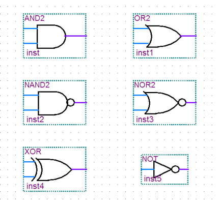
基本门电路
library IEEE;
use IEEE.std_logic_1164.all;

entity door is
    port(a,b: IN std_logic;
           y: OUT std_logic);
end door;

architecture dataflow of door is
begin
    y<=a nand b; --把 NAND 换成 and、or、nor、xor、xnor 即可
end dataflow;
RTL 就是对应的门:
编码器与译码器
encoder 和 decoder 要分清:
- inputs 是 「a group of binary codes」 的是 decoder
- inputs 是 「a group of signals in different logic levels」 的是 encoder
- binary 说明是一个二进制数,而 signals 只是独立的信号
--38 decoder 不存在优先级,所以用 case
architecture behav of decoder_38 is
signal indata:std_logic_vector(2 downto 0);
begin
    indata<=c & b & a;
    process(indata, g1, g2a, g2b)
    begin
        If (g1='1'and g2a='0' and g2b='0') then
            case indata is
                when "000"=>  y<="11111110";
                when "001"=>  y<="11111101";
                when "010"=>  y<="11111011";
                when "011"=>  y<="11110111";
                when "100"=>  y<="11101111";
                when "101"=>  y<="11011111";
                when "110"=>  y<="10111111";
                when "111"=>  y<="01111111";
                when others=> y<="XXXXXXXX";
            end case;
        else y<=" 11111111";
        end if;
     End process;
End behav;
RTL 图:第一个 IF 综合成一个 MUX21;后面 case 综合成 8 个 MUX81,每个 MUX81 负责 y 的 1 位。
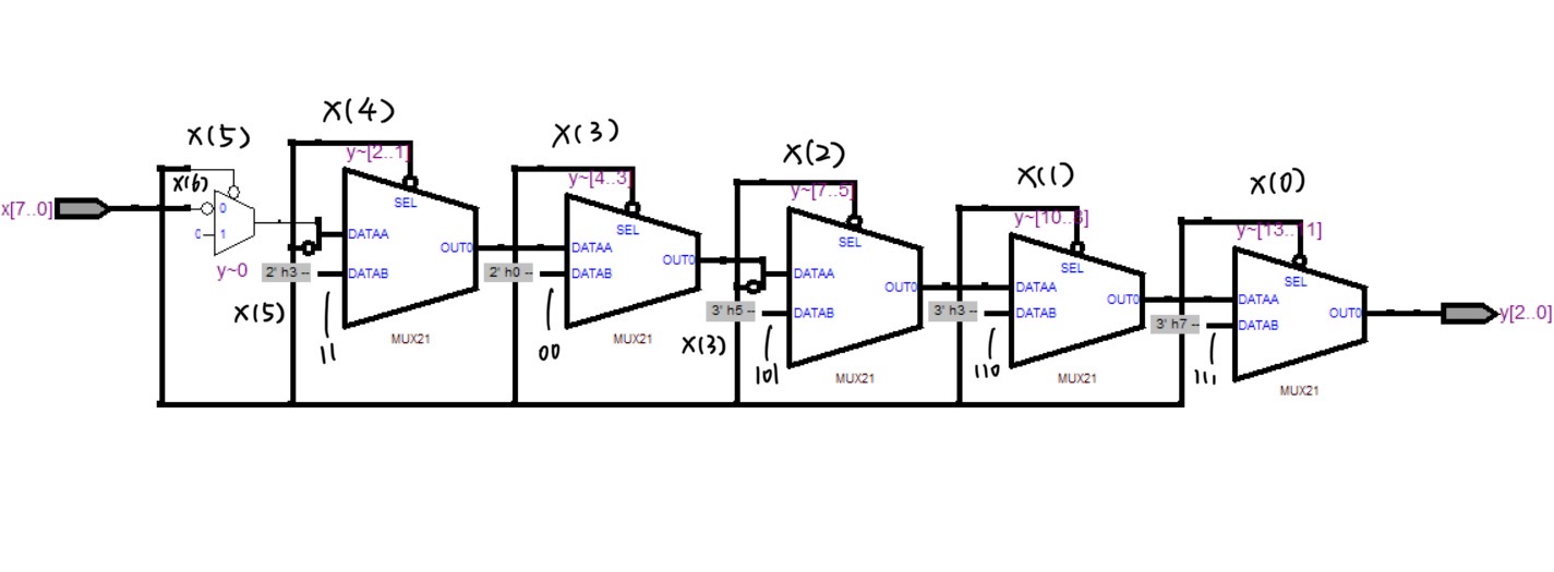
--优先级编码器
architecture behav of encoder is
begin
    y<= "000" when x="00000001" else
        "001" when x="00000010" else
        "010" when x="00000100" else
        "011" when x="00001000" else
        "100" when x="00010000" else
        "101" when x="00100000" else
        "110" when x="01000000" else
        "111" when x="10000000" else
        "ZZZ";
end behav;

--也可以用 process + if-elsif-else 来实现
architecture behav of encoder is
begin
    process(x)
    begin
        if (x(0)='0') then y<="111";
        elsif(x(1)='0') then y<="110";
        elsif(x(2)='0') then y<="101";
        elsif(x(3)='0') then y<="100";
        elsif(x(4)='0') then y<="011";
        elsif(x(5)='0') then y<="010";
        elsif(x(6)='0') then y<="001";
        elsif(x(7)='0') then y<="000";
        else y<="XXX";
        end if;
    end process;
end behav;
RTL 图:如果是用 when-else 实现,RTL 图很复杂(所以考试就别用了);如果是用 if-elsif-else 实现,则是 8 个 MUX21级联,越优先的越靠后(经过优化后只需 6 个 MUX21,并且也很复杂)。
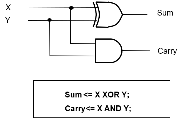
半加器与全加器
半加器:sum 用异或,carry 用与
architecture behav of halfadder is
begin
    sum <= x xor y;
    carry <= x and y;
end behav;
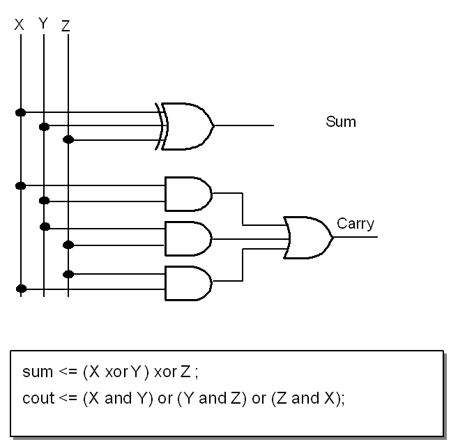
全加器:
architecture behav of fulladder is
begin
    co <= (a and b) or (b and ci) or ( a and ci); --有两个 1 即可
    sum <= a xor b xor ci; --奇数个 1
end behav;
注:多输入异或门:当输入中有奇数个 1 时输出 1
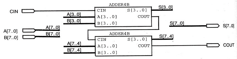
Sequential adder V.S. parallel adder
- Sequential adder is in cascade of full adders, low speed.
- Parallel adder has parallel logic for carry bit generation. Fast computation.
- Parallel adder needs more logic resources than sequential adder.
串联的 4位并行加法器:
三态门:
process (din,en)
begin
    if (en='1') then
        dou<=din;
    else
        dout<='Z';
    end if;
end process;
第四章 时序逻辑
一些概念的比较:
- 同步与异步
- Synchronous: The register actions are triggered by clock changes only (synchronized by the clock).
- Asynchronous: Asynchronous sequential logic is not synchronized by a clock signal; the circuit output can change directly in response to input changes.
- Moore 与 Mealy
- Moore: The output depends on memory state only.
- Mealy: The output depends on both memory state and the input.
名词解释:
- Latch:锁存器
- Flip-Flop:触发器
- Register:寄存器
- Counter:计数器
- Multiplier:乘法器
检测时钟上升沿触发的方法:
- 如果时钟不是
std_logic,是bit:process(clk) begin if (clk'event and clk='1') then ... end if; end process --or process(clk) begin if clk='1' then ... end if; end process --or process begin wait until clk'event and clk='1'; ... end process - 如果时钟是
std_logic:process(clk) begin if rising_edge(clk) then ... end if; end process;
注意以下几点:
- 每个进程只能有一个边沿检测的 if 语句或 wait 语句
- 边沿检测的 if 语句后面不加 else (但可以有 elsif)
- 如果一个变量在 if 边沿检测语句中有赋值,就不能在同一进程中再读操作
- 边沿检测不是操作数,所以不能在前面加 not 来检测下降沿,而是用
falling_edge(clk)或clk'event and clk='0' clk'event可以用not clock'stable代替
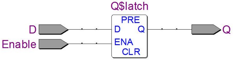
Latch
D-Latch
architecture behav of D_latch is
begin
    process(D, Enable)
    begin
        if (Enable='1') then Q<=D;
        end if;
    end process;
end behav;
RTL 图:直接画一个 D-Latch 框即可:
补充带 reset 和 preset 的 D-Latch
architecture behav of D_latch is
begin
    process(D, Enable)
    begin
        if reset='1' then
            y<='0';
        elsif preset='1' then
            y<='1';
        elsif (Enable='1') then
            Q<=D;
        end if;
    end process;
end behav;
SR-Latch
architecture behav of RS_latch is
begin
    process (R,S)
    variable rs: std_logic_vector(1 downto 0);
    begin
        rs:=R&S;
        case rs is
            when "00" => Q<='1'; Qbar<='1';
            when "01" => Q<='1'; Qbar<='0';
            when "10" => Q<='0'; Qbar<='1';
            when others=>null;
        end case;
    end process;
end behav;
RTL 图:case 有三个 when,对应三个 MUX21,Q 和 Qbar 各一个 D-Latch 用于存值。
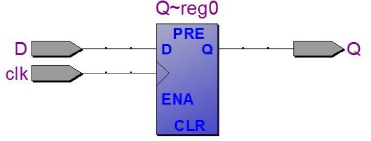
Flip-Flop
D-FF:就是将 D-Latch 的判断改成判断上升沿,同时将 D 从敏感参数表中删除
architecture behav of D_latch is
begin
    process(clk)
    begin
        if (clk='1') then Q<=D;
        end if;
    end process;
end behav;
RTL 图:直接画一个 D-FF 框即可:
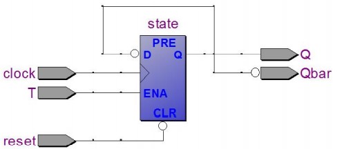
带 Qbar 和复位的 D 触发器:不能直接在 if 里面加 not Q,可以在 if 中赋给一个中间量,然后再在 if 外将中间量赋给 Q 和 Qbar,赋值的位置要求:
- 若中间量是 variable,因为立即变化,所以可以放在 process 内
- 若中间量是 signal,因为要等 process 结束后才变化,所以放在 process 外面
Architecture sig of D_FF is
    signal state: std_logic; --信号
Begin
    process( clock, reset)
    begin
        if (reset='0') then --复位不用考虑时钟
            state<='0';
        elsif rising_edge(clock) then
            state<=D;
        end if;
    end process;
    Q<=state; --放在 process 外
    Qbar<=not state; --放在 process 外
End sig;
Architecture var of D_FF is
Begin
    process(clock, reset)
        variable state: std_logic; --变量
    begin
        if (reset='0') then --复位不用考虑时钟
            state:='0';
        elsif rising_edge(clock) then
            state:=D;
        end if;
        Q<=state; --放在 process 外
        Qbar<=not state; --放在 process 外
    end process;
End var;
三个考点:
- 加一个信号作为中间值
- 复位是不用考虑时钟沿
- Q 和 Qbar 赋值的位置
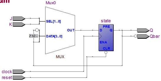
JK 触发器:同样是使用中间量
Architecture behav of JK_FF is
    signal state : std_logic ;
Begin
    process( clock, reset) is
        variable jk: std_logic_vector(1 downto
    0);
    begin
        jk:=J&K;
        if (reset='0') then state<='0';
        elsif rising_edge(clock) then
            case jk is
                when "11"=> state<=not state;
                when "10"=> state<='1';
                when "01"=> state<='0';
                when others => null;
            end case;
        end if;
    end process;
    Q<=state;
    Qbar<=not state ;
end behav;
RTL 图:
T-FF:
Architecture behav of T_FF is
Begin
    process(clock, reset)
        variable state: std_logic ;
    begin
        if (reset ='0') then state:='0';
        elsif rising_edge(clock) then
            if T=1'then
                state := not state;
            end if;
        end if;
        Q<=state;
        Qbar<= not state;
    end process;
End behav;
RTL 图:
复杂的
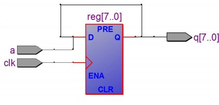
register 多位寄存器:D-FF 可以看作是 1 bit register,所以只需要将 D 和 Q 改成 std_logic_vector 即可。这里主要注意怎么用 generic
library ieee;
use ieee.std_logic_1164.all;

entity reg is
      generic( n: natural :=4 ); --实体类属中的常数
      port ( D: in std_logic_vector(n-1 downto 0);
          clock, reset : in std_logic;
          Q: out std_logic_vector (n-1 downto 0) );
end reg ;

architecture behav of reg is
begin
    process(clock, reset)
    begin
        if (reset='0') then Q<=( others=>'0'); --表示Q赋全'0'
        elsif rising_edge(clock) then
            Q<=D;
        end if;
    end process;
end behav ;
- 注意 others 的用法。
RTL 图就是多个 D-FF 并联,每个负责存一位。
Shift register 移位寄存器:
- SISO: Serial input -serial output
- SIPO: Serial input –parallel output
- PISO: Parallel input –serial output
以 SIPO 为例:
library ieee; use ieee.std_logic_1164.all;

Entity sipo is
    generic( n : natural :=8);
    port(a : in std_logic ;
         q : out std_logic_vector(n-1 downto 0);
        clk: in std_logic );
End sipo;

Architecture behav of sipo is
Begin
    process(clk)
    variable reg : std_logic_vector(n-1 downto 0);
    begin
        if rising_edge(clk) then
            reg : = reg ( n-2 downto 0) & a ; -- direction ?
         -- reg : = a & reg (n-1 downto 1); --right shift register
         end if ;
         q<= reg ;
    end process;
End behav;
RTL 图:输出的某些位与 a 拼接后作为输入(PPT 中的简化画法)
书上有另一种画法,是将 8 个 D-FF 级联,利用信号的延时来移位。
计数器:把移位寄存器中的「拼接」操作改成「加」即可,记得要用 std_logic_unsigned,这样才能对 std_logic_vector 进行加法。RTL 图如下:
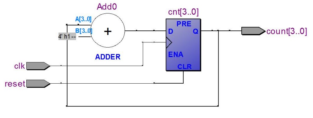
另一种方法是用 T-FF 级联,上一级 T-FF 的输出接下一级 clock,每级的 T<=’1’. 可以用 component+loop 实现。
这种方法的缺点是进位的时候会因为 Signal assignment delay 产生毛刺 glich
architecture ripple of counter is
    component T_FF is
        port( T : in std_logic ;
            clk:in std_logic;
            reset:in std_logic;
            Q : out std_logic;
            Qbar:out std_logic);
    end component ; --T-F.F. is instantiated as a component ;
    signal carry: std_logic_vector( n downto 0);
Begin
    carry(0)<=clk; -- pay attention to input signal clk
    g0: for i in 0 to n-1 generate --loop
        T1: T_FF port map ('1', carry( i ), reset, count( i ), carry( i+1 ));
    end generate g0;
End ripple;
第五章 状态机
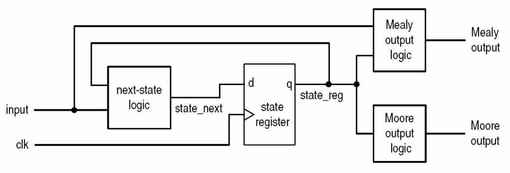
- next-state logic: 根据当前 state 和 input 来决定下一个 state
- state register:保存当前状态
- output logic:
- Moore: Output depends on present state only
- Mealy: Output depends on present state and input. If the input changes, the output can change during the current state
- 记忆方法:Moore 中的 o 代表 only
Race and Hazard:Signals through different paths arrive at the same node with time difference because of different propagation delays, which may cause transient error in output. 前半句是竞争,后半句是冒险,竞争导致冒险。
消除竞争与冒险的方法:Race and Hazard can be avoided by synchronous sequential logic(同步时序逻辑电路). 要求时钟周期满足:
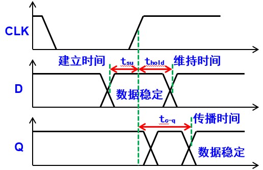
\[T>t_\text{su}+t_\text{cq}+t_\text{plogic}\]- $t_\text{su}$ 建立时间:Before the clock rising edge coming, the signal should keep unchanged for a while. 在时钟上升沿之前,输入信号改变后要保持一段时间
- ??? $t_\text{hold}$ 保持时间:After the clock rising edge coming, the signal should keep unchanged for a while. 时钟沿来了后,输入要继续保持一段时间
- $t_\text{c-q}$ 传播延时:The time that signals propagate on the paths.
- $t_\text{plogic}$ 最长传播延时:the worst time delay 从输入到输出中间的最长延时(plogic: propagation of logic)
另外,时钟周期有一定误差:
- Clock skew 时钟偏差 $\delta$:同一时钟输入到不同级的时间有误差
- Clock jitter 时钟抖动 $t_\text{jitter}$:一个时钟输入到同一级可能提早或延迟一点点
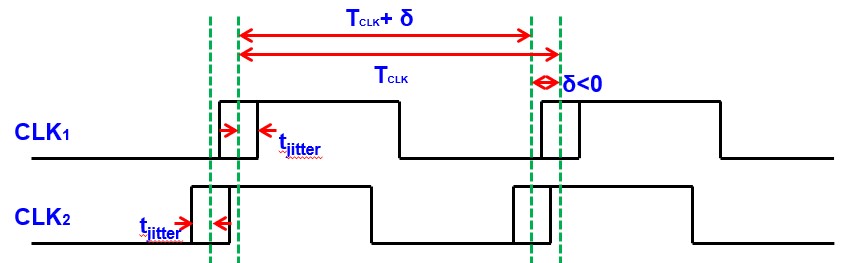
最短的时钟周期为:$T_\text{clk}+\delta-2t_\text{jitter}$,所以 $T_\text{clk}+\delta-2t_\text{jitter}>t_\text{su}+t_\text{hold}+t_\text{plogic}$
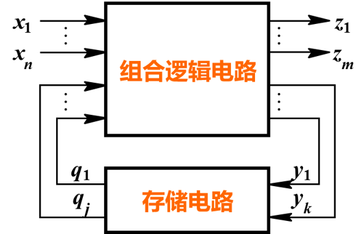
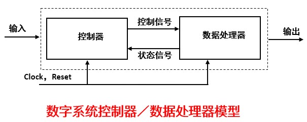
structure of state machine:
- Combination logic:
- Next state logic
- Output logic
- Memory units
分别对Next state logic,Output logic,Memory units写进程,这就是课本分三进程的分法,其中Next state logic,Output logic可以放在一个进程里,这样就是双进程的状态机了(考试要求掌握双进程状态机)
| 双进程 | 三进程 |
|---|---|
 |
|
ASM 图
| 状态框 | 判断框 | 条件框 |
|---|---|---|
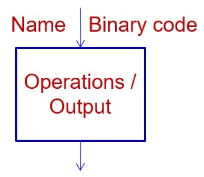 |
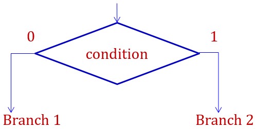 |
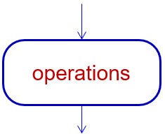 |
R<-0 表示在本状态给 R 赋值,重新赋值才改变C='1' 或 C 表示 C 在本状态为 1,过了本状态就为 0 |
条件框与上一个状态框同属于一个周期 | 条件框与判断看的一个分支相连,并与判断框同属于一个周期 |
如何根据电路画 ASM 图:先写驱动方程和输出方程,再画状态转换表,再画 ASM 图。
| 常见错误画法 | 正确画法 |
|---|---|
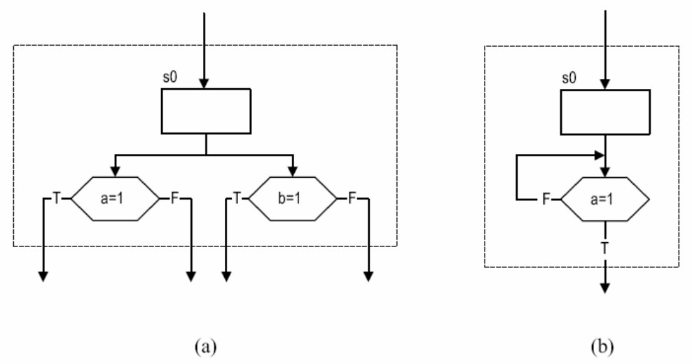 |
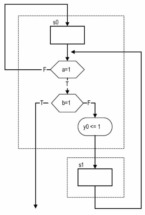 |
| ①状态、条件框只能有一个输出; ②输出一定要跟一个状态或条件框 |
①多个判断只能级联 ②表示当前状态不变的回路要回到状态框之前 |
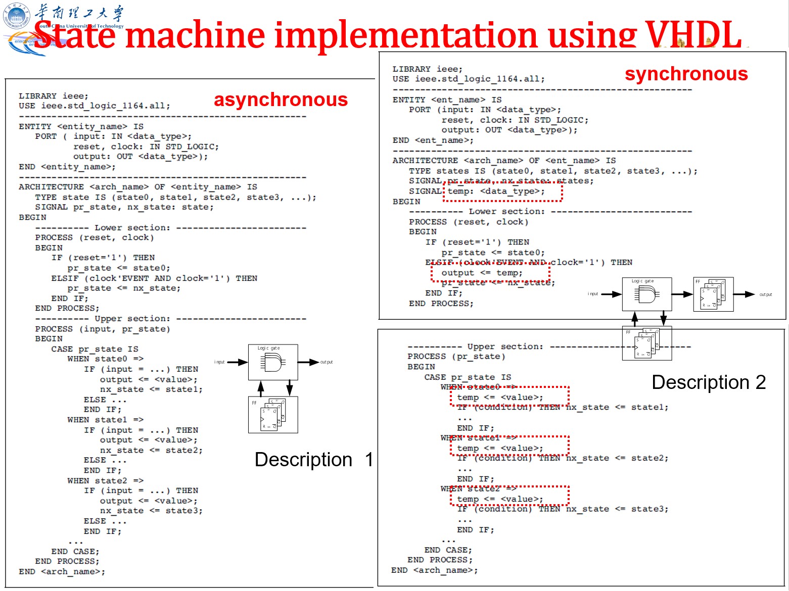
VHDL 描述状态机
双进程格式:存储状态一个进程,状态转变+输出一个进程
library IEEE;
use IEEE.std_logic_1164.all;

entity state_machine is
    port(
        reset: IN std_logic;
        clock: IN std_logic;
        DIN: IN std_logic;
        DOUT: OUT std_logic_vector(2 downto 0)
    );
end state_machine;

architecture asm of state_machine is
    type state_type is (s0, s1, s2, s3)
    signal present_state,next_state:state_type;
begin
    process(reset, clock)
    begin
        if reset='1' then
            state<=s0;
        elsif rising_edge(clock) then
            present_state<=next_state;
        --不完整 if 产生寄存器
        end if;
    end process;

    process(present_state, DIN)
        DOUT<=...; --默认情况,对应状态框的 C='1'(见前面笔记)
        case present_state is
            when s0=>
                DOUT<=...; --s0 状态的输出
                if DIN...
                next_state<=s1;
            when s1=>
                DOUT<=...;
                if DIN...
                next_state<=s2;
            when s2=>
                DOUT<=...;
                if DIN...
                next_state<=s3;
            when s3=>
                DOUT<=...;
                if DIN...
                next_state<=s0;
        end case
    end process
end asm;
三进程:把上面的 case 拆开来写。
library IEEE;
use IEEE.std_logic_1164.all;

entity state_machine is
    port(
        reset: IN std_logic;
        clock: IN std_logic;
        DIN: IN std_logic;
        DOUT: OUT std_logic_vector(2 downto 0)
    );
end state_machine;

architecture asm of state_machine is
    type state_type is (s0, s1, s2, s3)
    signal present_state,next_state:state_type;
begin
    process(reset, clock)
    begin
        if reset='1' then
            state<=s0;
        elsif rising_edge(clock) then
            present_state<=next_state;
        --不完整 if 产生寄存器
        end if;
    end process;

    process(present_state, DIN)
        case present_state is
            when s0=>
                if DIN...
                next_state<=s1;
            when s1=>
                if DIN...
                next_state<=s2;
            when s2=>
                if DIN...
                next_state<=s3;
            when s3=>
                if DIN...
                next_state<=s0;
        end case
    end process

    process(present_state)
        DOUT<=...; --默认情况,对应状态框的 C='1'(见前面笔记)
        case present_state is
            when s0=>
                DOUT<=...;
            when s1=>
                DOUT<=...;
            when s2=>
                DOUT<=...;
            when s3=>
                DOUT<=...;
        end case
end asm;
如何判断是 moore 还是 mealy:如果 if 只影响下一状态,则是 moore;如果 if 影响输出,则是 mealy.
另外,对于 moore 型,output 和 clock 是同步的;对于 mealy 型,output 可能同步也可能异步。上面的格式是异步的,如果要实现同步,必须引入一种中间的信号用于在 process 间传值。(见下图)
例子:序列检测器(moore):假设要检测 101
- 有重叠:
10101,有两个101- 状态:
0、1、10、101→10或1
- 状态:
- 无重叠:
10101,有一个101- 状态:
0、1、10、101→0或1
- 状态:
两类的区别仅在于最后一个状态的转移方向不同。另外,对某些子项多次出现的特殊序列,当输入不满足要求时,并不总是转移到初始状态。
State Coding Style
- symbolic coding
TYPE st1 IS ARRAY (0 TO 15) OF STD_LOGIC TYPE week IS (sun, mon, tue, wed, thu, fri, sat); SIGNAL present_state, next_state : week; - binary coding:由 EDA software 将 symbolic code 用 binary code 表示
- natural binary code:就正常而二进制
- Advantages: resource-efficient 适合小系统
- Shortcoming: 1.extra auxiliary logic is needed, 2.slow speed, 3.transitions from an odd to an even number may cause unpredictable effect.
- one-hot code:每一位表示一个状态
- Advantages: high speed 适合大系统
- Shortcoming: resource-intensive , complex logic and larger area inside a chip
- gray code:特殊的计数法,相邻状态只差一位
- Advantages:resource-efficient 适合小系统, 2-bit reversing is avoided in the transition between neighbor states, particularly useful in asynchronous output.
- Disadvantages: low speed.
- natural binary code:就正常而二进制
可通过 VHDL 的 attribute 设置编码方式:
attribute ENUM_ENCODING: STRING;
attribute ENUM_ENCODING of week: TYPE IS "111 001 010 011 100 101 110";
第七章 仿真与测试
(第六章是实验)
(1)Testing procedures using Testbench:
- DUT instantiation (DUT, Design Under Test)待测试的设计
- Stimulus generation 测试信号
- Apply the stimulus on DUT and observe its response 将测试信号输入到待测试的设计
- Compare the response with the expected result 比较输出与预期
例:简述仿真测试平台的基本架构(4分);试用VHDL语言编写测试平台文件(Testbench),要求testbench产生的时钟周期为100ns;复位信号0电平有效,且起始时刻为0,100ns后变为1。(12分) 被测文件的实体如下所示:
ENTITY sin_gen IS
    PORT
    (
        rst :  IN  STD_LOGIC;
        clk :  IN  STD_LOGIC;
        q :  OUT  STD_LOGIC_VECTOR(7 DOWNTO 0)
    );
END sin_gen;
library ieee;
use ieee.std_logic_1164.all;

---实体是空的
entity sin_gen_tb is
end sin_gen_tb;

architecture TB of sin_gen_tb is
    --component 把题目给的实体端口抄一次
    component sin_gen
    port(clk : in std_logic;
        rst : in std_logic;
        q :  OUT STD_LOGIC_VECTOR(7 DOWNTO 0));
    end component;

    --端口声明:输入端口加个 _t
    signal clk_t : std_logic;
    signal rst_t : std_logic;
    signal q_t : STD_LOGIC_VECTOR(7 DOWNTO 0);
begin
    --DUT 注意箭头
    DUT : sin_gen
        port map (clk => clk_t, rst => rst_t, q => q_t);

   --根据题目要求设计 clk_t 和 rst_t
    STIMULUS:process
    begin
        rst_t <= '0';
        wait for 100 ns; --0 fs
        rst_t <= '1';
        wait for 1 us;
        wait;
    end process;

    CLOCK: process
    begin
        clk_t <= '0';
        wait for 50 ns;
        clk_t <= '1';
        wait for 50 ns;
    end process;
end TB;
一些常用信号的产生:
- 时钟信号:简单信号可以用并行,复杂信号建议用串行。wait 用在串行,after 用在并行
--concurrent
--定义在 architecture 的 begin 前
constant clk_period : time := 40 ns;
--定义在 architecture 的 begin 后
clk2 <= '0' after clk_period/4 when clk2='1' else -- 1 持续 1/4 周期后变成 0
        '1' after 3*clk_period/4 when clk2='0' else -- 0 持续 3/4 周期后变成 1
        '1'; --从 1 开始

--sequential (process)
clk2_gen:process
constant clk_period : time := 40 ns;
    begin
        clk2 <= '1';
        wait for clk_period/4;
        clk2 <= '0';
        wait for 3*clk_period/4;
end process;

--另一种 sequential (process)
clk3_gen:process
constant clk_period : time := 40 ns;
    begin
        clk2 <= '1','0' after clk_period/4;
        wait for 3*clk_period/4;
end process;
- 复位信号:注意时间从哪开始算起
--concurrent
--时间从最开始算起(绝对时间)
reset1 <= '0','1' after 60 ns, '0' after 100 ns;

--sequential (process)
--时间从上个信号算起(相对时间)
reset2_gen:process
begin
    reset2 <= '0';
    wait for 60 ns;
    reset2 <= '1';
    wait for 40 ns;
    reset2 <= '0';
    wait; --一直等待下去,即不再重复运行该 process
end process;
- 相关信号(一个信号是另一个信号的延迟)
period1 <= '1' after 30 ns when period1='0' else
            '0' after 20 ns when period1='1' else
            '0';
period2 <= period1'delayed(10 ns);
第八章 综合
(1)Synthesis levels:
- high level synthesis 高层次综合
- translation from algorithmic(算法) behavior description to RTL description从算法级的行为描述转换到寄存器传输级描述的过程
- logic synthesis 逻辑综合
- translation from RTL description to logic gate netlist(网表)
- balance: higher speeds and smaller surface areas
- layout synthesis 版图综合
Normally, the physic hardware structure for a high level description is not unique, the main objective of high level synthesis is to find an optimal structure with respect to the cost and constraints(约束)综合结果不唯一,这点喜欢考选择题,选择题喜欢说它是唯一的,喜欢考选错误的,选它.
约束包括:芯片的 surface areas 和系统的 speeds
(2)什么可以被综合,什么不能被综合。
数据类型:
- 可被综合:
- bit , boolean , bit_vector
- character , string
- integer
- std_logic , std_ulogic_vector , std_logic ,std_logic, std_logic_vector
- signed , unsignd
- 不可被综合:FILE, Time(after/wait for语句,但 wait until 可被综合)
另外,有几个要注意的点:
- 只有某些 EDA 工具支持 2-D array
- integer should have a range (但好像不写也没事,默认 32bits)
数据对象:constant, variable, signal 的大部分语句都可被综合,但某些赋初值语句不会被综合:
Three cases of initial value assignment:
- default value by definition; 不可被综合,被忽略
- initialized value in declaration 不可被综合,被忽略
- explicit assignment in the beginning of a process. 可被综合
总的来说,在声明时(begin 前)附初值会被忽略,(begin 后)一般的附值(begin 后)就不会被忽略
Example:
--type  states  is (rst , fi , id , ie);
signal state : states ; --initial value of STATE is RST by default;

signal  z : bit_vector (3 downto 0) := "0000";   --initialized value in declaration

P1: process (A , B)
    variable v1 , v2 : std_logic ;
begin
    v1 := '0'  ;  v2 := '1';     --explicit assignment in the beginning of  a process
end  process P1;
sequential statement:
- if:完整 if 被综合成 mux 或基本逻辑门;不完整 if 会引入寄存器(每个赋值对应一个寄存器)
- case:mux
- loop:要求循环次数是确定的常数。 另外,next 和 exit 可被综合
concurrent statement:
- 赋值:变量/信号之间的赋值被综合成连线;常数赋值被综合成常数;逻辑表达式赋值被综合成组合逻辑电路
- process: a process includes at most one clock signal 一个process里只能有一个时钟信号
- when-else/with select:被综合成 mux
(3)一些选择题:
- 设计流程:原理图/HDL文本输入→适配→综合→功能仿真→编程下载→硬件测试;
数字系统的设计方法
简答题:
数字系统设计过程可以分为四个层次:
- 性能级
- 功能级
- 结构级
- 物理级
数字系统的一般划分:
单词
Decoder 译码器
Encoder 编码器
Flip-flop 触发器
Latch 锁存器
Register 寄存器
Combinational logic circuit 组合逻辑电路
Structure 结构
Reflect 显示
Feedback 反馈
Multiplexer 选择器
Tri-state gate 三态门
synthesize 综合
Simulation 仿真
Corresponding 相应的
Format 码制
Conversion 转换
Sensitivity list 敏感参数表
Operation 操作
Transmission 传输
Priority encoder 优先级编码器
Implementation 实现
Arithmetic 算术
Addition 加
Subtraction 减
Multiplication 乘
Division 除
Less significant stage 低位
Account for 考虑
Modular 模块化的
Component 组成
Multi-bit adder 多位加法器
Complex 复杂的
Execute 执行
Simultaneous 同时发生的
Parallel 并行的
Feature 特征
Execute concurrently  并行执行的
Sequential 时序的,顺序的
Optimize 优化
Configuration 配置
Declaration 声明,显示
Resemble 与。。相符
Optinal 可选择的
Arab number 阿拉伯数字
Generic 属性的,类的
Assign 赋值
Bi-directional 双向的
Abstraction 抽象
Comment 注释
Identifier 标识符
High impedance 高阻态
Positive 正整数
Enumeration 枚举
Consist 由。。组成
Fixed 固定的
Computation 计算
Waveform 波形
Hardware 硬件
Triggered 触发的
K-map 卡诺图
Equation 方程式
Finite 有限的
Race and hazard 竞争与冒险
Constrains 约束
Suspend 挂起
Top-down 自顶向下
Bottom-up 自底向上