SCUT’s VHDL course is teached in English. Therefore, most of this note will be in English. In case you misunderstand some important part, I’ll stress those part in Chinese.
Here is a breif introdution about VHDL, it’s a presentation from a Intel engineer. You can check it here 👉 https://youtu.be/zm-RA6BsYmc
One more thing, the textbook used in class is in Chinese, and I found an English one called Free Range VHDL. Most of my English note is base on this book
如果你真的不想看英语,可以直接去看 VHDL 复习
VHDL Introduction
Here are some terms you should know about VHDL.
VHDL stands for Very high speed integrated circuit Hardware Description Language. It’s use to describe models for both simulation and synthesis purposes.
VHDL is a HDL (Hardware Description Language), which is a software programming language htat is used to model a piece of hardware.
There is two ways to do modeling with HDL, one is Behavior Modeling, and the other is Structural Modeling.
- Behavior Modeling - A component is described by its input/output response
- Structural Modeling - A componet is described by itterconnecting lower-level components/primitives
Register Transfer Level (RTL) is a type of behavioral modeling, for the purpose of synthesis. With RTL, the design is described in terms of register stages with comet or blocks of logic between them.
Synthesis is a the act of translating this text-based HDL into a circuit and then optimizing that circuit.
Process is the basic unit of execution in VHDL.
Behavior Modeling and Structural Modeling
Behavior Modeling only specifies the functionality of the circuit, but does not actually indicate the structure of the circuit. The relationship between a component’s inputs and outputs is clearly defined at a high level without concering the hardware the hardware implementation details. The hardware implementation is left up to the interpretation of the compiler
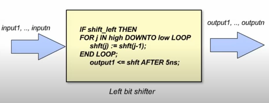
Structural Modeling, unlike behavioral modeling, specifies the functionality a circuit, but it goes further and calls out specific hardware implementation, including building blocks and their connections.
RTL Synthesis
During RTL synthesis, code is analyzed and equivalent logic structures are generated.
In the upper left of the picture below, you can see a process block with a case statement inside infering a four input MUX.
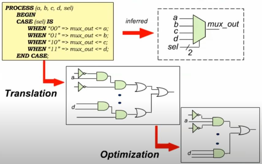
The synthesis tool recognizing the case statement structure performs two steps: translation and optimization.
During translation step, the synthesis tool directly translate the HDL code in a gate implementation.
During optimization step, the synthesis tool then tries to improve the logic by making it smaller or faster. For example, to make the logic smaller, it may try to remove redundant logic, or to make it faster, it may try adding some parallel structures to it.
Synthesis and Simulation Flows
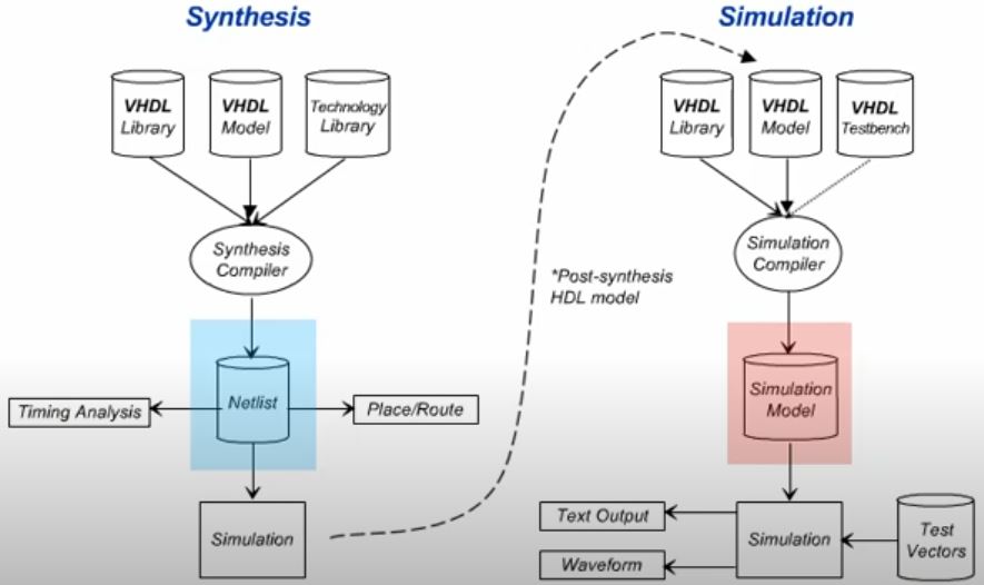
On the right, the simulation compiler take your VHDL code to create a simulator-specific simulation model, and then execute simulation on this model. Using this model allows a simulator to perform faster simulations than if it was tring read the code line by line.
During the simulation, the tool takes any test factors or stimulus provided by you and produces output waveform or text file that can be used to verify proper operation. As an alternative, you can also write your simulation stimulus using a generic VHDL code called a test bench. The test bench gets compiled along with the design, so that the stimulus is also in the compiled simulation model. The advantage of the test bench is that your stimulus is portable just like the design files, so you do not need to provide simulator specific test factors when you execute your simulation.
In the simulation flows, there’s no mention of hardware or target architecture. This is because the simulator just execute code as it is written. In a sense, it really does not care where the design is going as it is only concerned about interpreting the functional description by your VHDL code.
On the left, the synthesis compiler take the same VHDL design to produce a synthesized netlist. This netlist is yourdesign translaed into the primitives that make up the target a hardware architecture. Notes that a technology library was used. Every FPGA family has a different library that the synthesis tool use to map a design to its specific architecture. Using the generated synthesized netlist, the design can be placed and routed in the actual target device.
If post synthesis simulation is desired, the synthesis tool can produce a VHDL output file that represents the synthesized results, which can be taken back to the simulation simulation tool and re-simulated. This provides a check to ensure that the synthesis did not produce any errors.
Some VHDL Basics
VHDL contains two sets of constructs:
- Simulation: Only can be used for simulation.
- Snthesis & simulation: can be used for both.
VHDL is made up of reserved keyword like C, and it’s not case-sensitive. Evey VHDL statement must be terminated by a semicolon (;) with spaces used for readability which are ignored.
Comments can be added to the end of the line with a double dash (--) preceding it, or a comment block by preceding the comment with /* and ending them with */ similr to C.
Design Units
VHDL has four design units, which are:
- Package: Store reuseable Code like a toolbox. Consist of two parts: package declaration and package body.
- Entity: Used to define external view of a model.
- Architecture: Used to define the function of the model.
- Configuration: Used to associate an entity and an architecture. Multiple architretures can be associated to the same entity, and you can use the configuration to pick a specific entity-architecture pairing.
Entity
Here is the basic structure for an entity declaration.
ENTITY <entity_name> IS
  Generic delarations
  Port Declarations
END ENTITY <entity_name> ;
- Generic delarations: Used to pass informatio into a model.
- Port declarations: Used to describe the inputs and output.
you can close the entity in one of 3 ways:
END ENTITY <entity_name> ; --VHDL '93 and later
END ENTITY ; --VHDL '93 and later
END; --All VHDL versions
The port declaration is used to declare i/o to your entity and occurs within the entity declaration after the generic declaration.
ENTITY <entity_name> IS
  Generic Declarations
  PORT (
    SIGNAL clk, clr: IN BIT ;
    --Note: SIGNAL is assumed and is not required
    q: OUT BIT
    --Note: no ';' after the last port declaration
  );
END ENTITY <entity_name>
The structure for a port declaration goes <class> <object_name>: <model> <type>
<class>: what can be done to an object. (most alwaysSIGNAL, but it doesn’t have to be, so you almost never see th word SIGNAL actually apprear in an entity)<object_name>: the name of the i/o port.<model>: the direction of the port.IN: inputOUT: outputinout: bidirectional (both input and output)buffer: output with internal feedback
<type>: defines the type or the values that can be held by your i/o
The last port declaration is not followed by a semicolon.
Generics are values that could be passed into an entity at compilation time. We use them to make our entities parameterizable when designing hierarchically. We use the keyword GENERIC and within parentheses lists the generics.
ENTITY <entity_name> IS
  Generic (
    CONSTANT tplh, tphl:TIME:=5ns;
    --Note: CONSTANT is assumed and is not required
    tphz, tplz:TIME:= 3ns;
    default_value:INTEGER:=1;
    cnt_dir:STRINGL:="up"
  );
  PORT Declarations
END ENTITY <entity_name>
The generic declaration goes <class> <object_name> :<type>:=<intial value>
<class>: what can be done to the generic (which is usually CONSTANT and CONSTANT can be left out)<object_name>: the name of the generic<type>: the data type which specifies the values that your generic can hold<initial value>: optional
You can declare multiple generics in one line if they are the same type and initial value.
Architecture
Architecture describes the internal logic to your model. Architecture must be associated with an entity, but an entity can have multiple architecture associated with it.
When coding an architecture, there are two methods that can be used:
- Behavioral with the design described with an RTL and functional coding style
- Structrural which connects gates and components together like a netlist
- Hybrid: a mixture of both.
Similar to the entity block, the architecture can be terminated with several different methods depending on the version of VHDL.
END ARCHITECTURE  <architecture_name> ; --VHDL '93 and later
END ARCHITECTURE ; --VHDL '93 and later
END; --All VHDL versions
ARCHITECTURE <architecture_name> OF <entity_name> IS
    --Architecture declaration section example:
    SIGNAL temp:INTEGER:=1;
    CONSTANT load:BOOLEAN:=true;
    TYPE states IS (S1,S2,S3,S4);
BEGIN
    Process statements
    Concurrent procedural calls
    Concurrent signal asignment
    Component instantiation statements
    Generate statements
END ARCHITECURE <architecture_name>;
If you have multiple architecture for the same entity, then the name must be different. However, architecrue for the different entity can have the same name.
The local identifiers that you use inside the architecture are not ports of generics must be delared in the architecture declaration section before they can be used in the design. In the example, we see that we have a CONSTANT, a SIGNAL, and an enumerated data type.
After the architecture declaration section, you have the keyword BEGIN followed by the architecture body, which contains the executable lines of code within hte design made up of various typese of processes. And your architecture ends with the line END ARCHITECTURE <architecture_name>;
Configuration
Configuration unit is used to associate an entity to an architecture.
Since entities can have more than one architecture associated with them, the configuration assigns a unique name to a single entity-architecture pairing. Then, instead of haing to choose a pair, you simply select the configuration name and the tool understands which entity-architecture pair you are referring to.
CONFIGURATION <configuration_name> OF<entity_name> IS
    FOR <architecture_name>
        FOR <instance_name> : <component_name> USE <entity>(<architecture>)
        END FOR;
        FOR <instance_name> : <component_name> USE <configuration_name>
        END FOR;
    END FOR;
END CONFIGURATION <configuration_name>;
Configuration can also be used to associate an instance to another entity-architecture (component) hierrchically.

ENTITY cmpl_sig IS
    PORT (
        a, b, sel : IN BIT;
        x, y, z : OUT BIT
    );
END ENTITY cmpl_sig;

ARCHITECTURE logic OF cmpl_sig IS
BEGIN
    -- simple signal assignment
    x <= (a AND NOT sel) OR (b AND sel);

    -- conditional signal assignment
    y <= a WHEN sel='0' ELSE b;

    --selected signal assignment
    WITH sel SELECT
        z <= a WHEN '0'
             b WHEN '1'
            '0' WHEN OTHERS;
END ARCHITECTURE logic;

CONFIGURATION cmpl_sig_conf OF cmpl_sig IS
    FOR logic
    END FOR;
END CONFIGURATION cmpl_sig_conf;
Packages
Packages are a convenient way of storing and using information throughout an entire model.
Packages consist of:
- Package Declaration (Required)
- Package Body (Optional)
VHDL has two built-in Packages:
- Standard package: the build-in data types and operators.
- TEXTIO package: file operations
--Package Declaration
PACKAGE filt_cmp IS
    TYPE state_type IS (idle, tap1, tap2, tap3, tap4);
    FUNCTION compare (variable a, b : integer) RETURN boolean;
END PACKAGE filt_cmp

--Package Body
PACKAGE BODY filt_cmp IS
    FUNCTION compare (variable a, b : integer) IS
        VARIABLE temp : BOOLEAN;
    BEGIN
        IF a < b THEN
            temp := true;
        ELSE
            temp := false;
        END IF
        RETURN temp;
    END FUNCTION compare;
END PACKAGE BODY filt_cmp;
A LIBRARY is a directory that contains a package or a collection of packages. They are essentially directories where your packages are located.
VHDL have two types of libraries:
- Working libraries:
- Current project directory
- Resource libraries:
- STANDARD package
- IEEE developed packages
- Altera component packages
- Any LIBRARY of design units that is referenced in a design.
Before you can use any package, it must be compiled into a library. If you don’t compile it into a particular library name, then it will automatically be compiled into the working library named work.
To reference a package requires 2 clauses:
- LIBRARY clause:
LIBRARY <lib1_name>,<lib2_name>;- Defines the library name hat can be referenced
- Is a symbolic name to path/directory
- USE clause:
USE lib_name.pack_naem.object- Specifies the package and object in the library that you have specified in the library clause
Work and STD library is considered implicit libraries and do not need to be explicitly called out by your design.
Here is an example.
LIBRARY IEEE;
USE IEEE.STD_LOGIC_1164.ALL;
USE WORK.filt_cmp.ALL;
Placing the Library/Use clause 1st wil allow al following design units to access it.