Most programming languages are used to implement functionalities in a sequential manner, one instruction at a time. VHDL however describes hardware and so instructions are executed in a concurrent manner, meaning that all instructions are executed at once. (This is called parallelism or concurrency) Realizing this fact will help you to truly understand the VHDL programming paradigm and language.
Concurrent Statements
Whereas a processor steps one by one through a set of statements, VHDL has the ability to execute a virtually unlimited number of statements at the same time and in aconcurrent manner (in other words, in parallel).
Figure 4.1 shows a simple example of a circuit that operates in parallel.
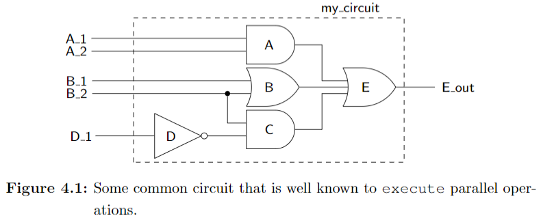
Listing 4.1 shows the code that implements the circuit shown in Figure 4.1.
--Listing 4.1
-- library declaration
library IEEE;
use IEEE.std_logic_1164.all;

-- entity
entity my_circuit is
port ( A_1,A_2,B_1,B_2,D_1 : in std_logic;
       E_out               : outstd_logic);
end my_circuit;

-- architecture
architecture my_circuit_arc of my_circuit is
    signal A_out, B_out, C_out :std_logic;
begin
    A_out <= A_1 and A_2;
    B_out <= B_1 or B_2;
    C_out <= (not D_1) and B_2;
    E_out <= A_out or B_out or C_out;
end my_circuit_arc;
since the statements are interpreted asoccurring concurrently: the order that these statements appear in your VHDL source code makes no difference. As a consequence of the concurrent nature of VHDL statements, the two chunks of code appearing below are 100% equivalent to the code shown in Listing 4.1.
--Listing 4.2
C_out <= (not D_1) and B_2;
A_out <= A_1 and A_2;
B_out <= B_1 or B_2;
E_out <= A_out or B_out or C_out;
--Listing 4.3
A_out <= A_1 and A_2;
E_out <= A_out or B_out or C_out;
B_out <= B_1 or B_2;
C_out <= (not D_1) and B_2;
Signal Assignment Operator <=
Algorithmic programming languages always have some type of assignment operator. In C or Java, this is the well-known “=” sign. VHDL uses two consecutive charactersto represent the assignment operator: <=. The operator is officially known as a signal assignment operator to highlight its true purpose.
With these new insights into VHDL, you should be able to understand thecode of Listing 4.1 and its relationship to its schematic shown in Figure 4.1.The statement G<=A AND B; indicates that the value of the signal named G represents an AND logic operation between the signals A and B.
There are four types of concurrent statements that are examined in this chapter. We have already briefly discussed the concurrent signal assignment statement which we will soon examine further and put it into the context of an actual circuit.
Concurrent Signal Assignment Statements
The general form of a concurrent signal assignment statement is shown in Listing 4.5. In this case, the target is a signal that receives the values ofthe expression. An expression is defined by a constant, by a signal, or by a set of operators that operate on other signals.
--Listing 4.5
<target> <= <express>;
Conditional Signal Assignment when
The term conditional signal assignment is used to describe statements that have only one target but can have more than one associated expression assigned to the target. Each of the expressions is associated with a certain condition. The individual conditions are evaluated sequentially in the conditional signal assignment statement until the first condition evaluates as true. In this case, the associated expression is evaluated and assigned to the target.
The syntax of the conditional signal assignment is shown in Listing 4.9.
--Listing 4.9
<target> <= <expression> when <condition> else
            <expression> when <condition> else
            <expression>;
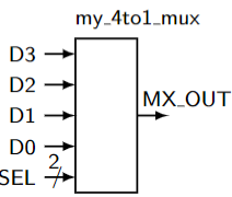
EXAMPLE 4. Write the VHDL code that implements a 4:1 MUX using a single conditional signal assignment statement. The inputs tothe MUX are data inputs D3, D2, D1, D0 and a two-input control bus SEL. The single output is MX_OUT.
--Listing 4.11: Solution of Example 4.
-- library declaration
library IEEE;
use IEEE.std_logic_1164.all;

-- entity
entity my_4t1_mux is
port(D3,D2,D1,D0 : instd_logic;
     SEL : instd_logic_vector(1 downto 0);
     MX_OUT : outstd_logic);
end my_4t1_mux;

-- architecture
architecture mux4t1 of my_4t1_mux is
begin
    MX_OUT <= D3 when (SEL = "11") else
              D2 when (SEL = "10") else
              D1 when (SEL = "01") else
              D0 when (SEL = "00") else
              '0';
end mux4t;
Note:
- The
=relational operator is used in conjunction with a bundle. In this case, the values on the bundle SEL are accessed using double quotes around the specified values. In other words, single quotes areused to describe values of individual signals while double quotes areused to describe values associated with multiple signals, or bundles.
--Listing 4.12: Alternative solution to Example 4 accessing individual signals
4.4 Conditional Signal Assignmentwhen41Listing 4.12: Alternative solution to Example 4 accessing individual signals.------------------------------------------------------------------- entity and architecture of 4:1 Multiplexer implemented using-- conditional signal assignment. The conditions access the-- individual signals of the SEL bundle in this model.------------------------------------------------------------------- library declaration
library IEEE;
use IEEE.std_logic_1164.all;

-- entity
entity my_4t1_mux is
port (D3,D2,D1,D0 : instd_logic;
      SEL         : instd_logic_vector(1 downto 0);
      MX_OUT      : outstd_logic);
end my_4t1_mux;

-- architecture
architecture mux4t1 of my_4t1_mux is
begin
    MX_OUT <= D3 when (SEL(1) = '1' and SEL(0) ='1') else
              D2 when (SEL(1) = '1' and SEL(0) ='0') else
              D1 when (SEL(1) = '0' and SEL(0) ='1') else
              D0 when (SEL(1) = '0' and SEL(0) ='0') else
              '0';
end mux4t;
Remember, a conditional signal assignment is a type of concurrent state-ment. In this case, the conditional signal assignment statement is executedany time a change occurs in the conditional signals (the signals listed in the expressions on the right-hand side of the signal assignment operator).This is similar to the concurrent signal assignment statement where the statement is executed any time there is a change in any of the signals listed on the right-hand side of the signal assignment operator.
Selected Signal Assignment with select
The syntax for the selected signal assignment statementis shown in Listing 4.13.
-- Listing 4.13
with <choose_expression> select
    target <= <expression> when <choices>,
              <expression> when <choices>;
EXAMPLE 5.: Write VHDL code to implement the function expressedby the following logic equation: $F3 =\overline{L}·\overline{M}·N+L·M$. Use only selected signal assignment statements in your VHDL code.
--Listing 4.14: Solution of Example5.
-- library declaration
library IEEE;
use IEEE.std_logic_1164.all;

-- entity
entity my_ckt_f3 is
port ( L,M,N : instd_logic;
       F3    : outstd_logic);
end my_ckt_f3;

-- architecture 1
architecture f3_1 of my_ckt_f3 is
    signal A1, A2 :std_logic; -- intermediate signals
begin
    A1 <= ((NOT L) AND (NOT M) AND N);
    A2 <= L AND M;
    F3 <= A1 OR A2;
end f3_1;

-- architecture 2
architecture f3_2 of my_ckt_f3 is
begin
    F3<=((NOT L)AND(NOT M)AND N)OR(L AND M);
end f3_2;

-- architecture 3
architecture f3_3 of my_ckt_f3 is
begin
    F3 <= '1' when (L = '0' AND M = '0' AND N = '1') else
          '1' when (L = '1' AND M = '1') else
          '0';
end f3_3;

-- architecture 4
architecture f3_4 of my_ckt_f3 is
begin
    with ((L ='0' and M ='0' and N ='1') or (L ='1' and M ='1')) select
        F3 <= '1' when '1',
              '0' when '0',
              '0' when others;
end f3_4;

-- architecture 5
architecture f3_5 of my_ckt_f3 is
    signal t_sig :std_logic_vector(2 downto 0); -- local bundle
begin
    t_sig <= (L & M & N); -- concatenation operator
    with (t_sig) select
        F3 <= '1' when "001" | "110" | "111",
              '0' when others;
end f3_5;